Theory of Operation
Functional Description
3
3-11
3-9. Continuity Measurement
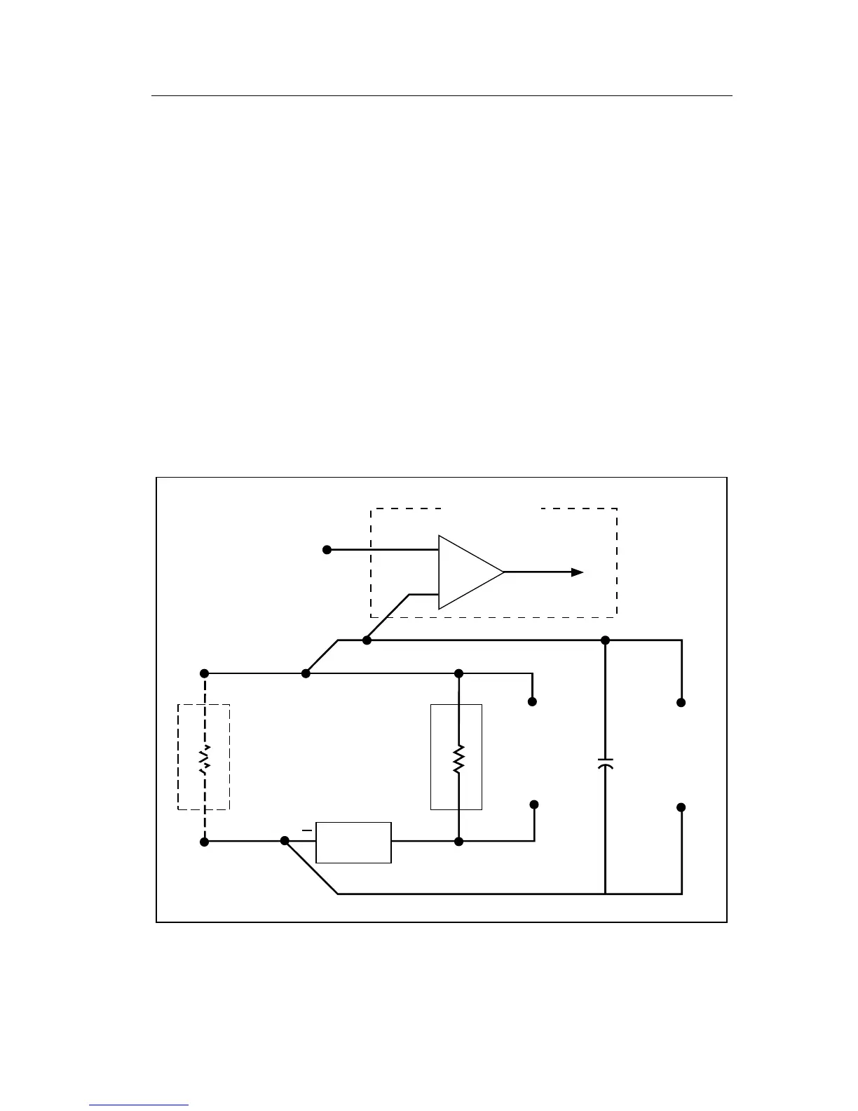
Continuity measurement is a voltage comparison made in the resistance
mode as illustrated in Figure 3-6. The 8062A determines whether continuity
exists in the circuit under test by comparing the voltage drop across the
external circuit with a continuity reference voltage. If the voltage drop across
the external circuit is less than the reference voltage, the comparator sends
the appropriate signal to the continuity logic. The continuity logic notifies
the microcomputer which turns on the visible indicator (the full-length bar
across the top of the display). If the audible indicator is enabled, the
continuity logic enables the tone generator.
The direction threshold is typically 50% of the full scale resistance range
selected. When the 8062A detects continuity for brief intervals (50
µ
s or
greater), the microcomputer extends the visible and audible indication to a
minimum of 200 ms to allow easy perception by the operator.
Continuity
Ref V
To
Continuity
Logic
Comp.
CM+
CM-
Unknown
Resistor
Known
Ref
Resistor
Ohms
Source
V/Ω/S
+
Common
ORef +
ORef -
Known
V Ref
to A/D
Converter
Unknown
V to A/D
Converter
Internal to the MAC
LO
HI
dy30f.eps
Figure 3-6. Resistance/Continuity Measurement