Maintenance
Performance Tests
4
4-15
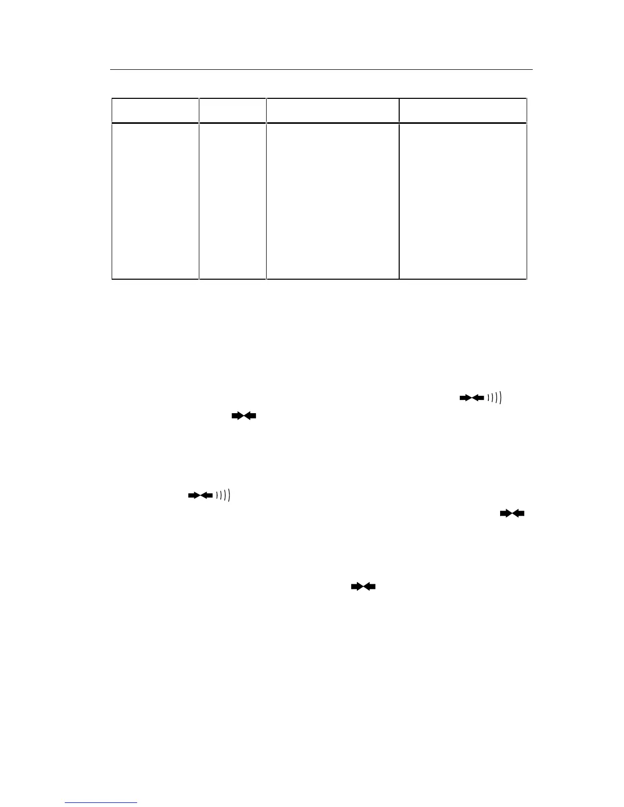
Table 4-3. Resistance Test
Step Range Input Resistance Display Limits
1
2
3
4
5
6
7
8 (optional)
9 (optional)
200Ω
200Ω
2 kΩ
20 kΩ
200 kΩ
MΩ
MΩ
MΩ
MΩ
short circuit
100.00Ω
1.0000 kΩ
10.000 kΩ
100.00 kΩ
1.0000 MΩ
10.00 MΩ
40.0 MΩ
290 MΩ
0.00 to 0.04
99.86 to 100.14
.9988 to 1.0012
9.988 to 10.012
99.88 to 100.12
.9978 to 1.0022
9.95 to 10.05
39.3 to 40.7
282 to 298
4-16. Continuity Test
Use the following procedure to verify proper operation of the continuity
function:
1. Connect the UUT and the DMM Calibrator as shown in Figure 4-4.
2. Select the resistance function and the 2 k
Ω
range. Press the
button once. The symbol should appear on the display.
3. Apply a resistance of 100.0
Ω
. The long bar across the top of the display
should appear on the display immediately. A reading of .0997 to .1003
should appear shortly thereafter (negating any test lead resistance).
4. Press the
button to enable the audible continuity (the 100.0
Ω
still applied). The
R
symbol should appear on the display with the
symbol. The tone should sound.
5. Remove the connections to the input of the UUT. The tone should stop
and the bar should disappear from the display. The display should
indicate OL (overrange) along with the
and
R
symbols.
4-17. Current Test
Use the following precautions to verify proper operation of the dc and ac
current functions:
1. Connect the UUT and the DMM Calibrator as shown in Figure 4-5.