Performance Tests
Performance Test 3
3-67
MHz
Frequency Counter
Front
Rear
10 MHz Output from
Frequency Standard
External
Reference
Frequency
Input
Instrument
hpn391.eps
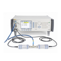
Figure 3-18. Equipment Connections - Microwave Output Frequency Accuracy Test Part A
4. Set the UUT as follows:
Ref Frequency Input Disabled
Mode Leveled Sine
Signal Microwave Output
Ref Frequency Input Disabled
Frequency 10 kHz
Level +13 dBm
Output OPER
5. Set the frequency counter as follows:
Function Freq A
Slope Positive
Coupling AC
Input Impedance 50
Ω
Attenuation 1x
Trigger Mode Auto
6. Set the output frequency of the UUT to each of the frequencies listed in part
A of Table 3-28. At each frequency allow the frequency counter to take
several readings and settle; the settled reading must be within the tolerance
shown. At 1 GHz connect the UUT Microwave output to the counter channel
C input and select the counter Freq C function.
7. Set the UUT output to STBY. Remove all connections to the frequency
counter.

 Loading...