96000 Series
Service Manual
3-68
Table 3-28. Frequency Accuracy Test – Microwave Output
Part UUT Frequency Tolerance
A
10 MHz 9.999 999 500 – 10.000 000 500 MHz
1 GHz 0.999 999 950 0 – 1.000 000 050 0 MHz
B
5 GHz 4.999 999 750 0 – 5.000 000 250 0 MHz
6.036 GHz 6.035 999 698 2 – 6.036 000 301 8 MHz
8.048 GHz 8.047 999 597 6 – 8.048 000 402 4 MHz
9.52 GHz 9.519 999 524 0 – 9.520 000 476 0 MHz
10 GHz 9.999 999 500 0 – 10.000 000 500 0 GHz
11.32 GHz 11.319 999 434 0 – 11.320 000 566 0 GHz
12.072 GHz 12.071 999 396 4 – 12.072 00 603 6 GHz
13.5 GHz 13.499 999 325 0 – 13.500 000 675 0 GHz
15 GHz 14.999 999 250 0 – 15.000 000 750 0 GHz
16 GHz 15.999 999 200 0 – 16.000 000 800 0 GHz
18.108 GHz 18.107 999 094 6 – 18.108 000 905 4 GHz
19.04 GHz 19.039 999 048 0 – 18.108 000 905 4 GHz
20 GHz 19.999 999 000 0 – 20.000 001 000 0 GHz
21.84 GHz 13.499 999 325 0 – 21.800 001 090 0 GHz
22.64 GHz 21.799 998 910 0 – 13.500 000 675 0 GHz
24 GHz 23.999 998 800 0 – 24.000 001 200 0 GHz
26.5 GHz 26.499 998 675 0 – 26.500 001 325 0 GHz
8. Set the UUT output to STBY. Remove all connections to the frequency
counter.
9. Connect the 10 MHz output from the frequency standard to the EXT REF IN
on the spectrum analyzer (rear panel) using a BNC male – male cable
assembly. Set the spectrum analyzer for external frequency reference.
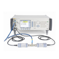
10. Connect the UUT Microwave output to the input of the spectrum analyzer.
See Figure 3-19 for equipment connections.

 Loading...