96000 Series
Service Manual
3-22
Instrument
Power Meter
Power Sensor
50 Leveling
Head
N Adapter
hpn212.eps
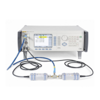
Figure 3-6. Equipment Connections - 50 Ω Leveling Head, High Frequency Level Accuracy Test
Points (96040A and 96720A)
10. Configure the Power Meter to indicate readings in dBm. Enter the
measurement frequency (0.1 MHz) into the Power Meter to enable cal factor
(frequency) correction.
Note
The recommended Power Meter has Power Sensor calibration
factors stored internally in the sensor. Setting the input frequency in
the Power Meter automatically selects the appropriate cal factor for
the measurement. However, the Power Sensor may also be
accompanied by a table of calibration factors which must be applied
externally.
11. Allow the Power Meter reading to settle. Record the measured level in dBm
as P
2
for use later in this procedure.
Note
The Power Meter autorange boundary may coincide with a
measurement point. To avoid unwanted Power Meter autoranging,
manually lock the Power Meter range once the 100 kHz reading is
obtained and maintain the Power Meter range lock for all
subsequent frequencies at this amplitude.
12. Set the UUT frequency to the first test frequency listed in Table 3-11.
13. Enter the measurement frequency into the Power Meter and allow the Power
Meter reading to settle. Record the measured level in dBm as P
3
. Calculate
the UUT output P
out
= P
1
+ (P
3
– P
2
).
14. Check that the value of P
out
is within the tolerance shown in Table 3-11.

 Loading...