Performance Tests
Performance Test 3
3-23
Note
The insertion loss of the 50 Type-N female-to-female adapter must
be taken into account at each measurement frequency.
15. Set the UUT to the next frequency point at this amplitude listed in Table 3-11,
and repeat steps 13 through 15.
16. Set the UUT to 100 kHz at the next amplitude listed in Table 3-11, and repeat
steps 11 through 15.
17. Set the UUT output to STBY.
Table 3-11. 50 Ω Leveling Head, High Frequency Level Accuracy Test Points, Thermal Power Sensor
(96040A and 96720A)
Amplitude Frequency Reading P
out
Tolerance
+16 dBm
100 kHz P
2
Reference
10 MHz P
3
±0.05 dB
100 MHz P
3
±0.05 dB
300 MHz P
3
±0.07 dB
1.4 GHz P
3
±0.20 dB
+13 dBm
100 kHz P
2
Reference
10 MHz P
3
±0.05 dB
100 MHz P
3
±0.05 dB
300 MHz P
3
±0.07 dB
1.4 GHz P
3
±0.20 dB
3 GHz P
3
±0.30 dB
4 GHz P
3
±0.30 dB
+3 dBm
100 kHz P
2
Reference
10 MHz P
3
±0.05 dB
100 MHz P
3
±0.05 dB
300 MHz P
3
±0.07 dB
1.4 GHz P
3
±0.20 dB
3 GHz P
3
±0.30 dB
4 GHz P
3
±0.30 dB
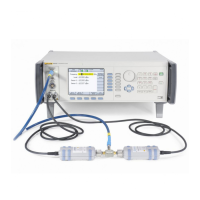
18. Connect the 50 Ω Leveling Head to the 50 Ω diode Power Sensor via a
precision 50 Ω Type-N female-to-female adapter. See Figure 3-6 for
equipment connections.
19. Set the UUT as follows:
Mode Leveled Sine
Frequency 100 kHz
Level -7 dBm
Output OPER
20. Enter the measurement frequency (0.1 MHz) into the Power Meter to enable
cal factor (frequency) correction.

 Loading...