96000 Series
Service Manual
3-26
Low-Level Test Points (steps 28-36)
28. Connect the Leveling Head to the RF INPUT of the Measuring Receiver and
connect the REF FREQUENCY OUTPUT (rear panel) from the UUT to the
Spectrum Analyzer Ext Ref In (on rear). See Figure 3-7 for equipment
connections.
Front
Rear
RF Input
50
Leveling Head
Ext Ref Input
Spectrum Analyzer
Ref Frequency
Output
Instrument
hpn207.eps
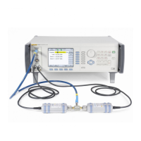
Figure 3-7. Equipment Connections - 50 Ω Leveling Head, Low Level Accuracy Test Points
Note
Low-level measurements are made with a Measuring Receiver,
relative to levels previously measured with the Power Sensor and
the Measuring Receiver. Two levels (-37 dBm from the Power
Sensor and -75 dBm from the Measuring Receiver) are used as
reference points to provide the required UUT hardware configuration
for the subsequent tests. The value of the output level at -37 dBm
measured in steps 19 through 27 above and at -75 dBm measured
in steps 30 through 33 below will be used as references in the
following procedure, identified as P
-37
and P
-75
respectively for each
test frequency. It is important that the correct sequence is followed
as described.

 Loading...