96000 Series
Service Manual
3-38
POWER
I
O
1000V RMS MAX 1000V RMS MAX
3V RMS MAX
INPUT 1 INPUT 2
SHUNT
HI
LO
GUARDGROUND
10V PEAK
MAX
WIDEBAND
7V RMS MAX
INPUT1
SHUNT
INPUT2 WBND EX GRD
2.2 mV 22 mV 220 mV
7 mV 70 mV 700 mV
2.2 V 22 V 220 mV
7V 70V 700V
1kV RESET
EX TRIG
TRIG
VIEW
REF
UTIL
MENUS
SPEC
CLEAR
DELETE
ENTER
01 2 3
4
5
6
7
89
+/-
.
V
H Z
SHELL FLOATING
10V PEAK MAX
Clear
Ref
INPUT2
Avg
Ref
(Vin - Ref) / Ref
-27.0 PPM
Range
2.2V
AUTO
5790A
AC MEASUREMENT
STANDARD
Instrument
AC Measurement Standard
75 Leveling
Head
75 Feedthrough
Common Mode Choke
Insert common mode choke here
5790A Input 1
5790A Ground
Terminal
hpn223.eps
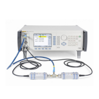
Figure 3-10. 75 Ω Equipment Connections - Leveling Head, Low Frequency Level Accuracy Test
Points (96040A and 96270A)
4. Set the UUT output to the next frequency listed in Table 3-17 for this test
amplitude.
5. Repeat step 3 and confirm that the measured output level is within the
tolerance shown in Table 3-17.
6. When the test frequency is 100 kHz, record the measured level in dBm as P
1
for use later in this procedure.
7. Repeat steps 2 through 6 for the next test amplitude listed in Table 3-17,
applying the 5790A 2.2 mV range linearity error correction at levels
below -40 dBm.

 Loading...