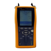
DTX Series CableAnalyzer
Technical Reference Handbook
10-2
Figure 10-1. Network Module Features
Installing and Removing the Network
Module and Optional SFP Module
See Figure 10-2.
Install the network module only in the main tester.
Install an optional SFP (small form pluggable) module to
test fiber links.
WCaution
Leave the module bay cover in place when a
module is not installed.
Put the dust cap on the SFP port when an optical
module is not installed. Put the dust cap on the
optical module when not connected to a fiber.
amd38f.eps
A
The link LED is green when the tester is receiving link
pulses from the network.
B
8-pin module jack (RJ45) for connecting to twisted
pair networks.
C
Port for inserting an optional small form pluggable
(SFP) optical module for testing fiber links.

 Loading...