Getting Acquainted
Basic Features
1-11
1
A
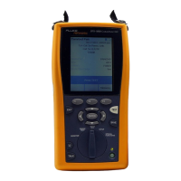
Connector for twisted pair interface adapters.
B
Cover for the module bay. Slide off the cover to install
optional modules, such as the fiber module.
C
Bail.
D
DTX-1800 and DTX-1200: Slot and activity LED for the
removable memory card. To eject the card, push in
then release the card.
E
USB ( ) and RS-232C ( ): DTX-1800,
DTX-1200) ports for uploading test reports to a PC and
updating the tester’s software. The RS-232C port uses a
custom DTX cable available from Fluke Networks. See
Chapter 13 for more information.
F
Headset jack for talk mode.
G
Connector for the ac adapter. The LED turns on when
the tester is connected to ac power.
•
Red: Battery is charging.
•
Green: Battery is charged.
•
Flashing red: Charge timeout. The battery failed to
reach full charge within 6 hours. See “If Something
Seems Wrong” on page 13-7.

 Loading...