approximately 2 times. The trigger level circuits generate a DC level
that has the same attenuation. This means that the output of this cir
-
cuit has a range of –1.6 V to +1.6 V with a resolution of maximum
0.3 mV. A dual 8-bit DAC is used. The DACs only generate voltages
between 0 and +1.6 V, but by using a X2 amplifier and an offset shift
of 50%, the voltage range of –1.6 V to +1.6 V is achieved. The supply
voltages to the trigger level circuits are filtered by R and C to prevent
noise originating in the digital circuitry from influencing the trigger
levels. The ground plane under the trigger level circuits is separated
from the rest of the ground plane, and the planes are connected only
at the front of the counter.
The trigger level circuits consist of the following:
–
Resistor network R57 to R68 for generating the reference volt
-
ages 0.04 V, 0.22 V, 0.59 V, and 1.6 V.
–
Three multiplexers (U3) to select one of the levels. With this
arrangement there is a total trigger level range of
–1.6 V to +1.6 V.
–
A double DAC (U4).
–
Two current-to-voltage converters U6. These circuits convert
the current at the IOUT pins of the DACs to a voltage. This
signal has a range of 0 V to approximately 1.6 V.
–
Two amplifiers, U7, with an amplification of X2, to generate a
signal with a range of 0 V to 3.2 V. Resistors R69 and R70 set
the reference voltage to the amplifier to get the 50 % offset
shift. To get exact voltages, 0.5 % precision resistors are used:
R73-R75, R78-R79 and R80-R82, R85-R86.
–
The zero adjust of the trigger levels is done with trimmer po
-
tentiometers R69 and R70 connected to the amplifiers in U7.
–
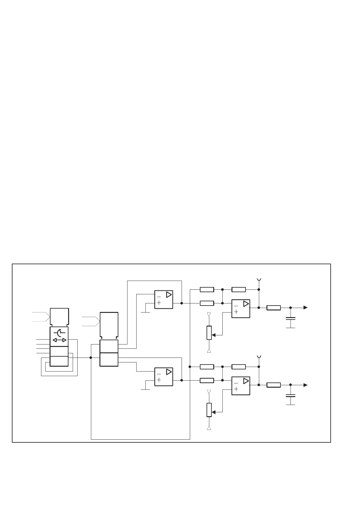
Two low-pass filters R87-C29 and R88-C30.
4-8 Hardware Functional Description
-5.2
+5
VREFR FB
IOUT
D0- D7
+DACA
VREFR FB
IOUT
U4
U6
U3
R88
U7
R69
Trig ger level Comp I
AD0-AD2
AD0 - A D8
-5.2
+5
R85-R86
R82
U7
R70
1.6V
0 .59V
0 .22V
0 .04V
R87
R78-R79
Trigger level
Comp II
Compar ator I
Comparator II
R75
R73-R74
R80-R81
C29
C30
U6
Fig. 4-9 Trigger level circuits.