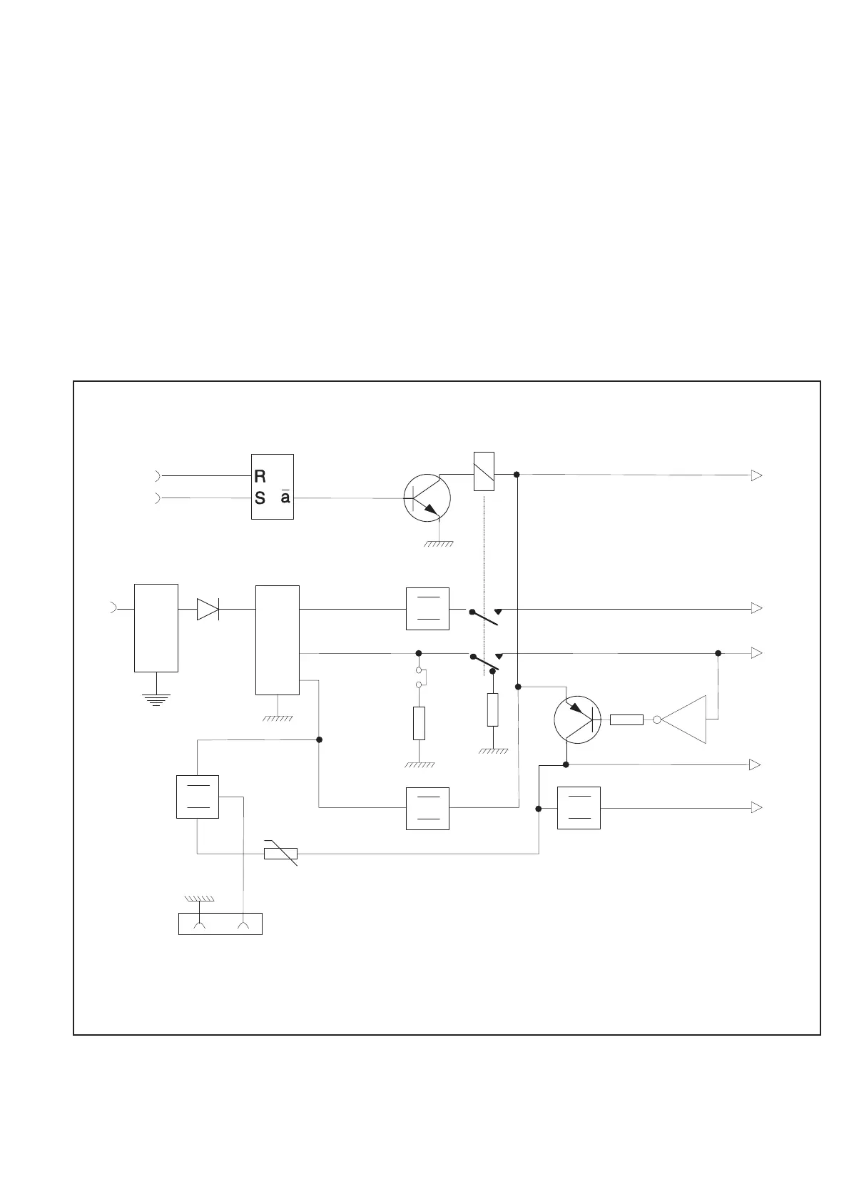
Power Supply
n
General survey
The power supply generates four regulated DC supply voltages to the
counter, as well as some other supply voltages for special purposes.
The power supply block also contains the ON/STANDBY logic.
The main building block of the power supply is a primary switch
mode power module (U39). The line power AC voltage (90 V to
265 V) is rectified to a DC voltage before it is fed to the power mod
-
ule.
After a line power filter in the power inlet, a fuse of 1.6 AT and an
NTC resistor protect the power supply. The fuse F1 should only blow
if a catastrophic error occurs on the primary side of the power supply.
A short-circuit on the secondary side should not affect the primary
side. To minimize the inrush current to the capacitors at the connec
-
tion of the power cord, an NTC resistor (R148) is used. The resis
-
tance is 15 Wwhen the resistor is cold but decreases to a few ohms as
it is warmed up by the steady-state current.
The AC voltage is rectified in the bridge rectifier D9 and filtered in
C64. C65 suppresses noise from D9. L6 and C82-C83 serve as a fil
-
ter at the input of U39.
All inputs and outputs of the power module have HF chokes. The
module is mounted with distance washers on the main board.
From the module there are three DC voltages outputs. One of those is
regulated (+ 5 V) and the others are unregulated. These voltages will
vary with input line voltage, the current at+5V,andattheunregu
-
lated voltages. The output marked +15 will be approximately +18 V,
and the output marked –7 will be approximately –8 V. The outputs
are filtered; HF is filtered by C70-C73, and LF is filtered by L7-L9
and C74-C76.
Hardware Functional Description 4-9
U
U
U
+7 V
+12 V
+12 V*
+5 V
-5.2 V
Fan
PM6685R
only
On
M
Filter&Fuse
Power Module
ains Inlet
Stand by
U40B
D9
U39
+15
+5
-7
U43
U41
*) for ON/STBY control & OCXO
U21A&Q17
Q14
K5
U42
J31
K5
R130-R145
U
R149-R155
J15
R156
+-
Q5-Q6
Fig. 4-10 Power Supply.