Input Amplifier
n
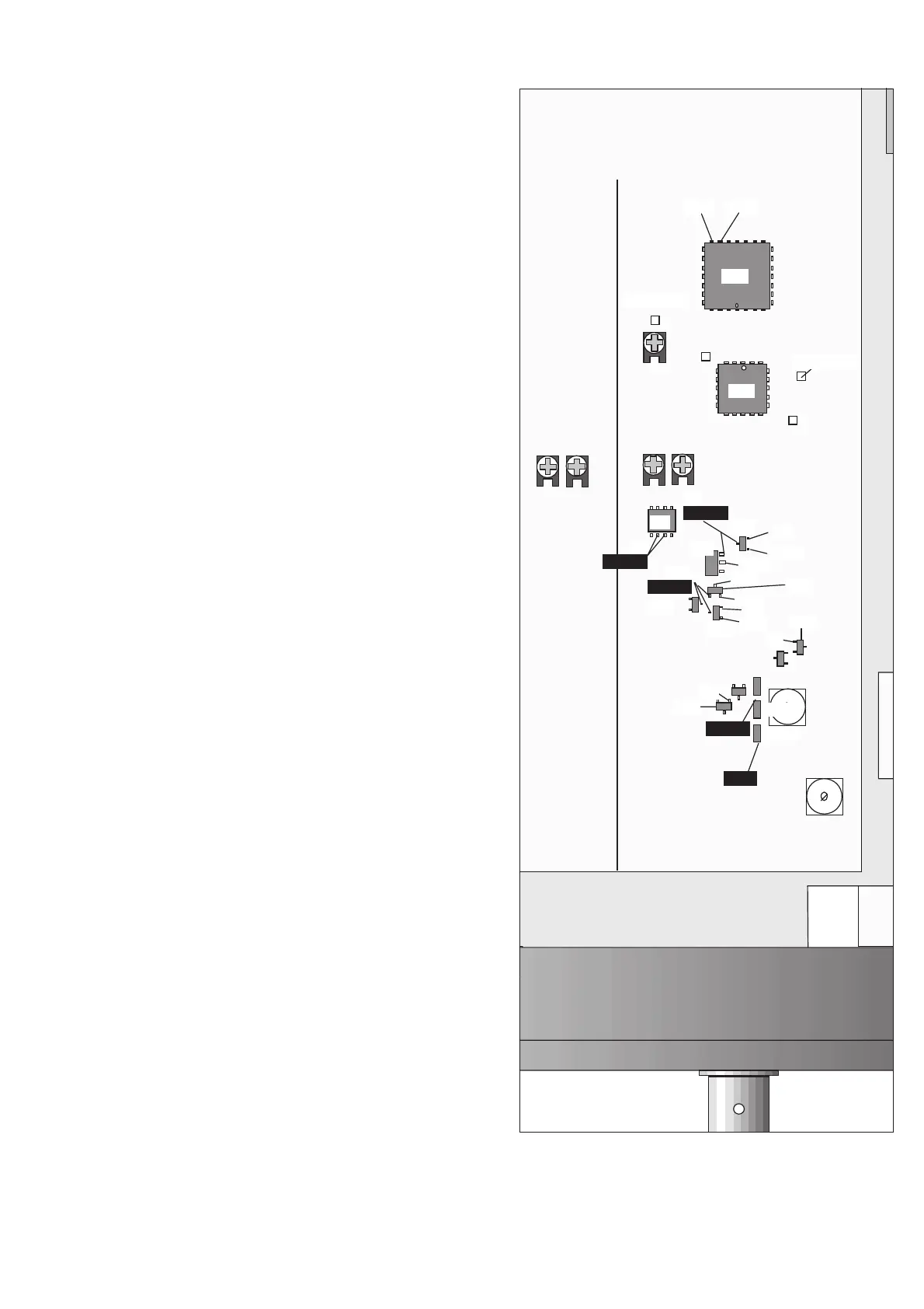
A Input Check
DC levels
–
Switch on the counter.
–
Press LOCAL/PRESET and ENTER.
–
Deselect AUTO and set the sensitivity to 1 Vrms.
–
Measure the DC voltages according to Fig. 5-5. Use the DMM
with a 10 kW resistor in series with the test cable.
AC levels
–
Connect a 1000 Hz sine wave signal with an amplitude of
1V
pp
to Input A.
–
Measure the AC-levels according to Fig. 5-5. Use the oscillo
-
scope and a 10 MW probe.
If you find any fault, continue with traditional troubleshooting tech
-
niques and replace defective circuits. Also refer to Input Amplifiers
A and B in Chapter 4, Circuit Descriptions.
Troubleshooting 5-7
TP27, -1.4V
U8
Q1
Q3
Q4
U1
U9
Q13
0V
0.3Vpp
1.5V
0.6Vpp
0.6Vpp
0.8V
7V
0V
0.6Vpp
1Vpp
4.3V
0.8V
0.4V
-3V
-2.3V
Q2
TP26, -1.4V
TP11
TP10
2V
-2V
D4
D3
D1
D2
-1.7V -0.9V
R23
R31R33
R91
R22
C1
C2
Fig. 5-5 Typical voltages, input amplifier.