n
Prescaler 3.0 GHz, PM9624
See Chapter 2, Performance Check, for verification.
This prescaler cannot be repaired in a local workshop. It must be sent
to your Fluke representative for repair.
GPIB Interface and Analog Output
n
General Remark
If the GPIB board is suspected to be faulty, be sure the basic instru
-
ment is OK by performing a few functional checks after the ribbon
cable has been disconnected from J18.
n
Analog Output
The microcontroller generates a PWM signal that is applied to pin 1
on U101. The frequency is approximately 20 Hz, but the duty cycle is
dependent on several factors like the frequency of the measured sig
-
nal, the measurement time, and the selected scaling factor.
The PWM signal is converted to a DC voltage between 0 V and
4.98 V by integration, first in a passive RC network (R101, C103,
R102, C102 and then in an active integrator U103.
Setup
–
Connect the counter to line power.
–
Switch on the counter.
–
Press PRESET and then ENTER.
–
Connect a DMM to the BNC output BU102.
–
Activate the analog output.
–
Select AUX MENU.
–
Press DATA ENTRY p/q until the display reads ANA
-
LOG OUT.
–
Press ENTER
–
Press DATA ENTRY p/q to select ON.
–
Press ENTER.
–
Press DATA ENTRY p/q until the display reads 1.0
-3
V.
–
Press ENTER.
–
Connect a LF synthesizer to Input A on the counter.
–
Set the synthesizer to 500 Hz, 1 V
PP
–
Read the DMM result. The voltage should be 2.49 V ± 35 mV.
Minor deviations can depend on the settings of the trimmer potenti
-
ometers for ZERO and FULL SCALE. See Chapter 6, Calibration
Adjustments, for a decription of the procedure to follow.
Large deviations indicate a fault. Trace the signal through the inte
-
gration chain with traditional troubleshooting techniques and replace
defective circuits. The duty cycle at U101:1 should be 50 %. Also re
-
fer to GPIB Interface Including Analog Output in Chapter 4, Circuit
Descriptions.
n
Bus Interface
A simple method to check the most fundamental functions of the in
-
terface is to send the standardized query message
*
IDN? and check
the response string.
Setup
–
Make sure you have access to a PC with GPIB capability.
–
Check that there is a program installed that can send simple
commands entered via the keyboard and that can receive and
display the response strings.
–
Connect the GPIB connectors of the counter and the PC by
means of a standard GPIB cable.
–
Set the address switches on the counter (the five rightmost
ones seen from the rear) so that their binary weight corre
-
sponds to the wanted decimal value between 0 and 30.
–
Send the command
*
IDN? to the counter and observe the re
-
sponse string. See the programming manual for more
information on the response format and contents.
–
You can also try the command
*
OPT? to get a listing of in
-
stalled options (except OCXO).
If you find a fault, continue with traditional troubleshooting tech
-
niques and replace defective circuits. Try to exercise the address/data
bus by writing small program loops. Look for stuck nodes with an
oscilloscope.
5-8 Troubleshooting
0
Sensitivity
-10 dBm
-20 dBm
-30 dBm
-40 dBm
-50 dBm
1GHz 2GHz
2.5 GHz
Frequency
Fig. 5-6 Specified and typical sensitivity of input C
(PM9624).
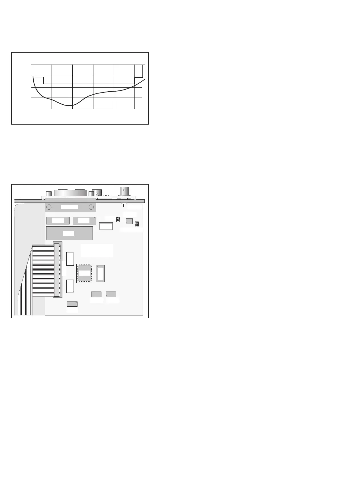
U109
U101
U106
BU101
U103
Zero
GPIB
BU102
BU103
Full Scale
U107
U111
U108
U113
U116
U117
U114 U115
Fig. 5-7 Component layout, GPIB interface.