iTuner Manual
24
4.4 Tuning Commands
4.4.1 Introduction
iTuner calibration data are stored on the on-board flash memory (see chapter 6 for instructions
on calibrating the tuner). Memory size is large enough to store several hundred sets of
calibration data at different frequencies. Each calibration set may consist of a ‘primary’
frequency and up to 5 ‘secondary’ frequencies (harmonic or non-harmonic). The primary
frequency is used during calibration to determine the probe positions where calibration data are
measured. The location of the calibration points is chosen such way that we obtain a uniform
distribution of the reflection coefficient at the tuner reference port on the Smith Chart. The
probe has to travel half a wavelength (0.5in order to achieve a full 360 degree phase, thus,
the lower the primary frequency, the larger the horizontal travel required to do a full circle.
Tuning is only possible at the ‘primary’ frequency. Calibration data at the ‘secondary’
frequencies are used to calculate the load/source impedance seen by the device at these
frequencies, as well as the tuner losses.
Tuning at primary frequency
Determines calibration point location
Information only, cannot be used for
tuning
Up to 5 ‘secondary’ frequencies
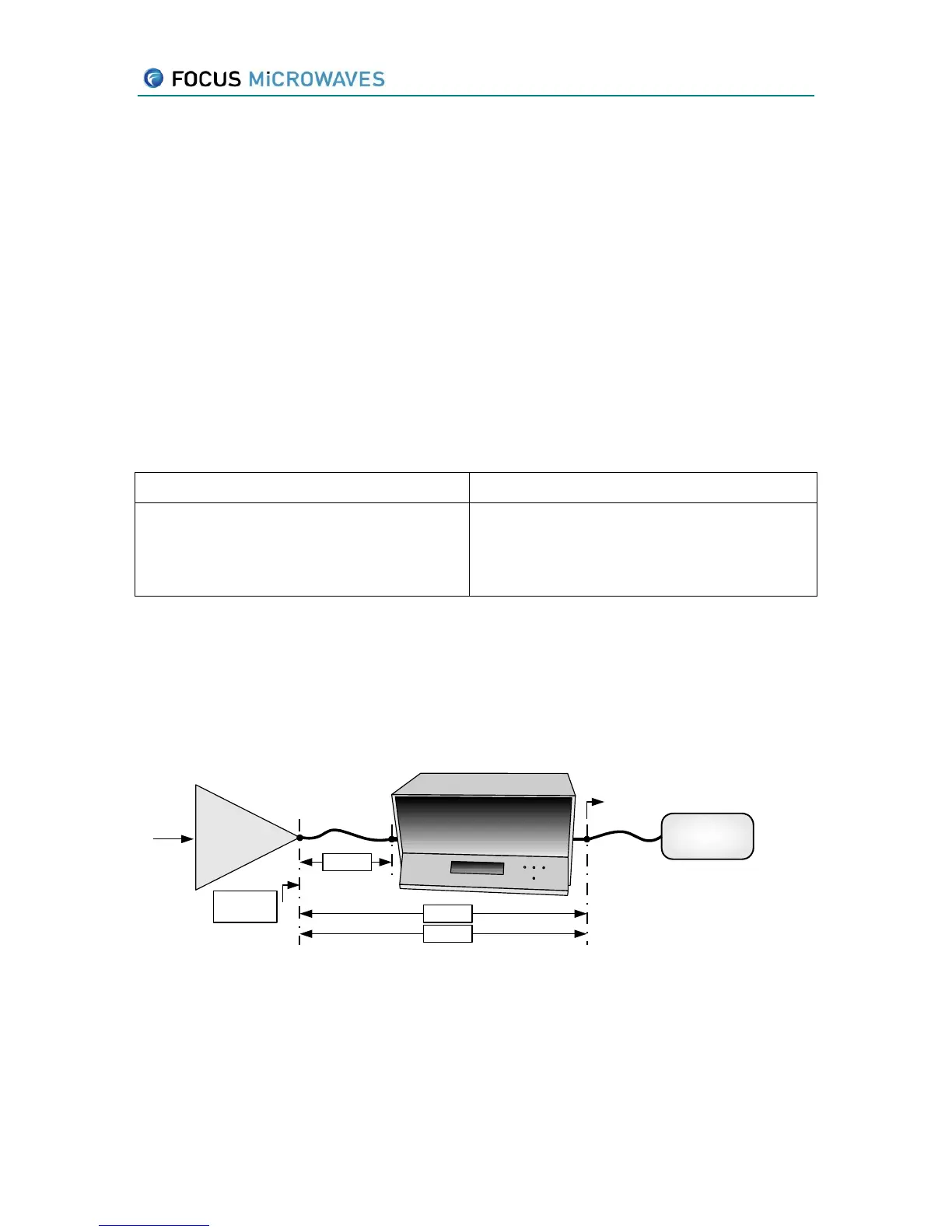
Tuner calibration is generally performed by selecting the reference plane at the input and
output connector. Often, adapters and cables have to be used to connect the tuner to the DUT,
thus we have to shift the reference plane for tuning.
Input
signal
DUT
Tuning
Reference
Plane
iTuner
Power
Meter
Adapter
SPAR?
GAMMA?
VSWR?
LOAD
LOSS?
Figure 4-1: Mode LOAD
Further, the reflection coefficient seen by the device also depends on the termination
connected to the output port of the tuner (
LOAD
in Figure 4.1).
By default, both the Adapter and the Termination are considered ideal components (S
11
=S
22
=0,
S
12
=S
21
=1,
LOAD
=0).