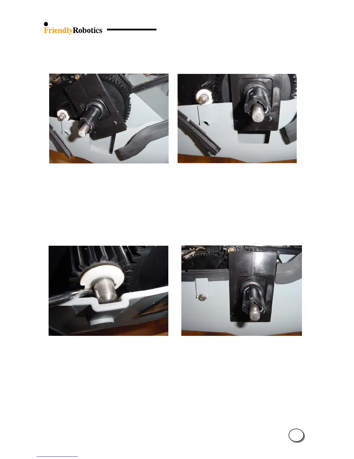
P. Insert the slider into the cavity of the base wall, as illustrated in Figure 4.2.6.1.4 below. Repeat
this step for the other side of the unit.
Q. Straighten the slider and position it as illustrated in Figure 4.2.6.1.5 below.
Figure 4.2.6.1.4 Figure 4.2.6.1.5
Inserting the slider into place Slider in its insertion position
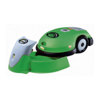
R. Using a wide flat screwdriver extend the base wall and insert the short shaft inside, as
illustrated in Figure 4.2.6.1.6 below.
S. Slide the short shaft all the way until it locks into its hole. Repeat the step for the other side of
the short shaft, as illustrated in Figure 4.2.6.1.7.
T. Replace the seal of the front bumper and the seal of the rear bumper so they will touch both
sides of the slider, as illustrated in Figure 4.2.6.1.7.
Figure 4.2.6.1.6 Figure 4.2.6.1.7
Moving the base wall to allow short shaft insertion Slider in its insertion position
U. Place the ground clearance adjustment handle to its middle position.
V. Repeat steps C to J in reverse order. Make sure the drive motor cables are connected to the main
board in the proper order – from to bottom: red, green, white and black (the colors are printed on
the board). Ensure that cable ties are placed tightly around the wires from the Wire Connectors.
W. Replace the cover as outlined in section 4.2.2.
X. Perform the ‘Drive motor test’ outlined in section 5.4.4.
Y. Complete the General Test as outlined in section 5.1.
4
24