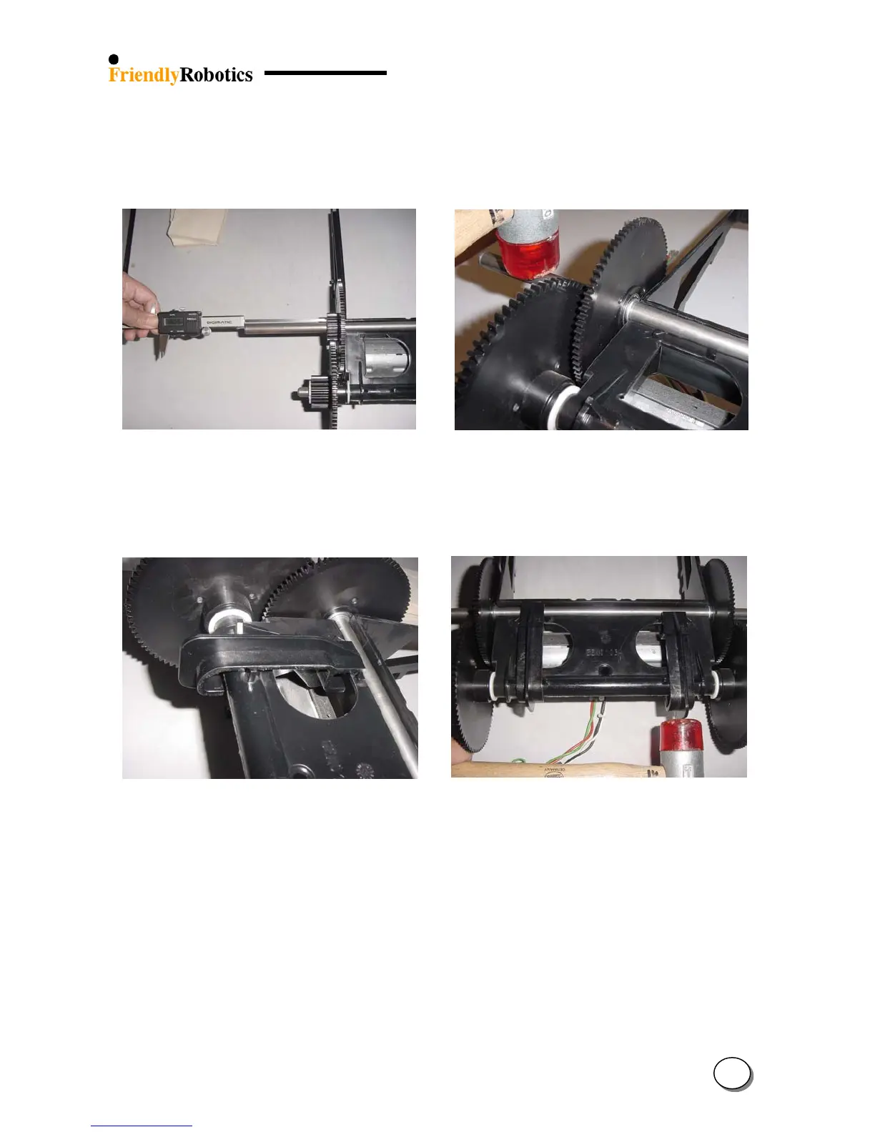
M. Center the new long shaft in its groove using a caliper. The measure from the shaft end to the
gear is 101 mm, as illustrated in Figure 4.2.6.3.11.
N. Once the long shaft has been centered, use the plastic hammer to force the shaft into its
groove, as illustrated in Figure 4.2.6.3.12.
Figure 4.2.6.4.11 Figure 4.2.6.4.12
Centering the long shaft Inserting the long shaft into the groove
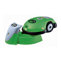
O. Take both clips and place them between the notches, as illustrated in Figure 4.2.6.3.13.
P. Use a plastic hammer to tap the clips into place, as illustrated in Figure 4.2.6.3.14.
Figure 4.2.6.4.13 Figure 4.2.6.4.14
Placement of the clips on the gear frame and shafts Tapping of the clips into place
Q. Return the gear case, as explained in section 4.2.6.1.
R. Return the drive wheels, as outlined in section 4.1.5.
S. Return the cover as outlined in section 4.2.2.
T. Perform the ‘Drive motor test’ outlined in section 5.4.4.
U. Complete the General Test as outlined in section 5.1.
4
30