G. Push the second side of the protrusion, as illustrated in Figure 4.2.9.4.
Figure 4.2.9.4
Pushing the protrusion –
2
nd
step
H. Pull down the two ‘T’ holders located next to each of the drive wheels. The faulty bumper will
become detached from the gray plastic base.
Bumper assembly
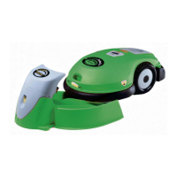
I. Support the Robomow on its side but be careful not to damage any of its exposed internal
parts. Place the bumper on the Robomow, as illustrated in Figure 4.2.9.5.
J. Take the new rear bumper and apply the soap and water solution on all seven holding
protrusions.
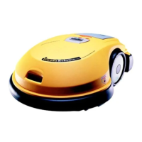
K. Insert the top of the ‘T’ holder into its place, as illustrated in Figure 4.2.9.6.
Figure 4.2.9.5 Figure 4.2.9.6
New bumper placement initial position Insertion of the ‘T’ holder
L. Place both (white or purple) bumper cables above the upper edge of the bumper.
M. Identify the holding protrusion closest to the inserted ‘T’ holder, use your thumb and press it
into its rectangular hole in the gray plastic base. At first press one side of the protrusion, as
illustrated in Figure 4.2.9.7.
4
37