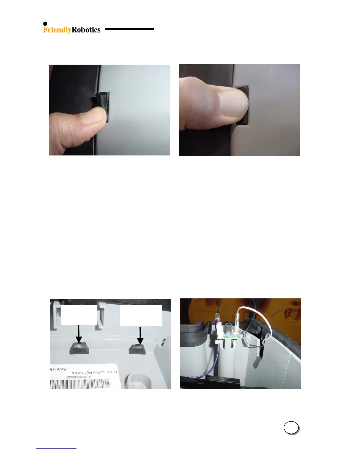
N. Once the first side of the protrusion is in the rectangular hole, press with your thumb the rest
of the protrusion into the rectangular hole, as illustrated in Figure 4.2.9.8.
Figure 4.2.9.7 Figure 4.2.9.8
Thumb pressing on one side of the protrusion Thumb pressing the entire protrusion
O. Move the other end of the bumper and insert the ‘T’ holder into its place as was explained in
item K above. Make sure both bumper cables are still placed above the upper edge of the
bumper.
P. Repeat steps M and N for the remaining six protrusions so the entire bottom edge of the
bumper is securely placed.
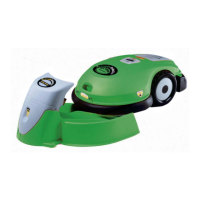
Q. Verify that all the protrusions went actually all the way, as illustrated in Figure 4.2.9.9.
On the left side is a properly seated protrusion and on the right side the protrusion requires
additional pressing/manipulation. Make sure all the protrusions look like the one on the left.
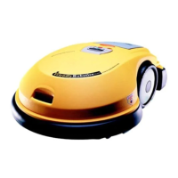
R. Connect both bumper cables. Make sure both cables coming out of the bumper are going
through the designated notch in the gray plastic base, as illustrated in Figure 4.2.9.10.
Proper
seating
Improper
seating
S. Replace the top edge of the bumper, above the ‘T’ holder areas, on the gray plastic base, as
illustrated in Figure 4.2.9.10.
Figure 4.2.9.9 Figure 4.2.9.10
Proper and improper seating of the protrusion 1
st
stage top bumper edge placement
4
38