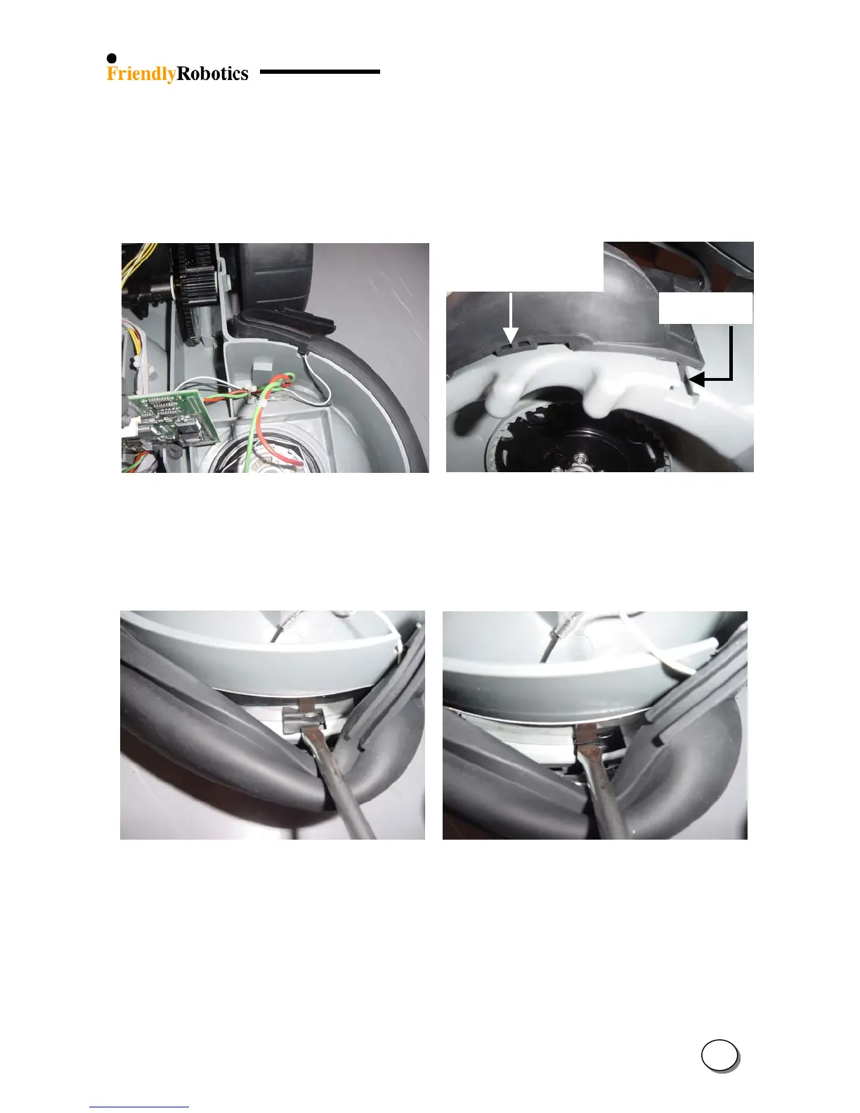
C. Disconnect both left and right bumper cables (white or purple) that are coming out of the front
bumper.
D. Peel off the “ears” that touch the slider seal on both sides of the Robomow, as illustrated in
Figure 4.2.10.2 below and the rest of the front bumper’s top edge.
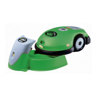
Underside of
holding protrusion
T’ holde
E. Identify the ‘T’ holder and the under side of the holding protrusion in the bottom side of the
bumper, as illustrated in Figure 4.2.10.3 below.
Figure 4.2.10.2 Figure 4.2.10.3
Peeled of front bumper’s top edge ‘T’ holder and protrusion’s under side
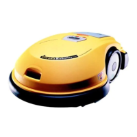
F. Using the wide flat screwdriver, push down one side of the protrusion, as illustrated in Figure
4.2.10.4.
G. Push the second side of the protrusion, as illustrated in Figure 4.2.10.5 below.
Figure 4.2.10.4 Figure 4.2.10.5
Pushing the protrusion – 1
st
step Pushing the protrusion – 2
nd
step
H. Pull down on the two ‘T’ holders located on each side of the bumper, as illustrated in Figure
4.2.10.3. The faulty bumper will become detached from the gray plastic base.
4
40