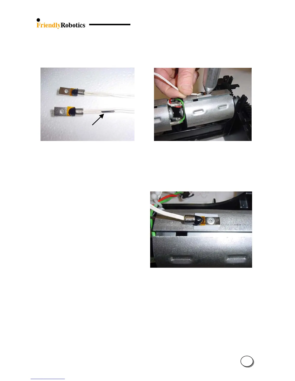
F. The Thermistor cable color is white. There is one side with black marking on the white cable,
as illustrated in Figure 4.2.11.4 below. Make sure the side with the black marking is attached
to the right mowing motor.
Mowin
side
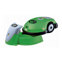
G. Attach the pop rivet with the Thermistor to the motor shading, as illustrated in Figure 4.2.11.5.
Figure 4.2.11.4
The side with the black
mark is connected to the
Mowing side
Figure 4.2.11.5
Attaching the Thermistor to
the drive motor shading
using pop rivet
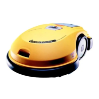
H. Repeat the same steps to attach the other Thermistor to the mowing motor shading. Confirm
the Thermistor is well attached and aligned, as illustrated in Figure 4.2.11.6.
Figure 4.2.11.6
Proper attachment of the
Thermistor to the Drive
motor shading
I. Replace the cover as outlined in section 4.2.2.
J. Perform ‘Thermistors test’ under the ‘Service’ menu (section 4.4.6).
K. Complete the General Test as outlined in section 5.1.
4
45