4
44
4.2.11 Thermistors assembly/replacement
Required tools: Wide flat screwdriver
External circlip pliers + Driller
Procedure duration: 30 minutes
NOTE: Read Service Bulletin #RL0340-10 - Thermistors Kit (SPP0020A) Installation
Instructions (Section 7.1) before starting this procedure.
Before starting the assembly of Thermistor to the Robomow, confirm the Main Board has the
connector to support the Thermistors connection.
A. Remove the Power Pack and the cover, as outlined in section 4.2.1.
B. Disconnect the Thermistors cable from the Main Board.
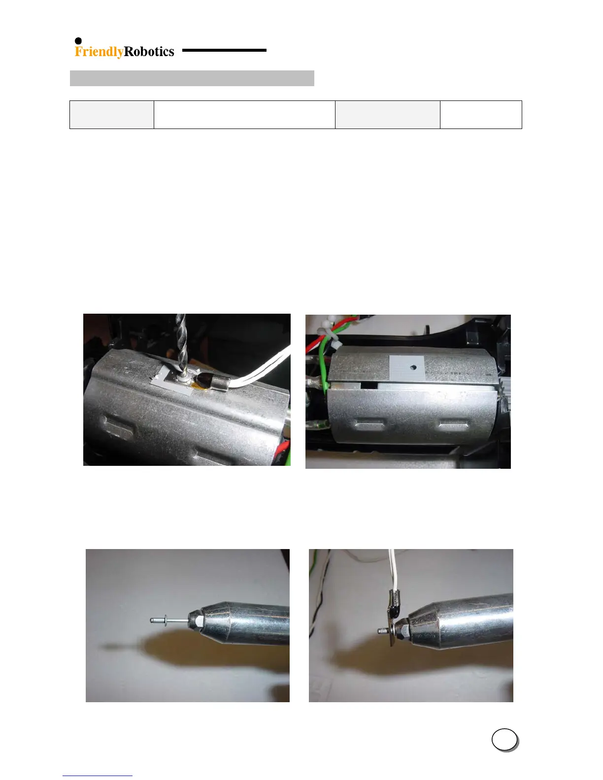
C. Drill the pop rivet, as illustrated in Figure 4.2.11.1, to release the Thermistor from the drive
motor shading. Vacuum the area inside the Robomow and around the gearbox - make sure
there are no metal residues from the drilling process.
D. Place the pad on the drive motor shading, as illustrated in Figures 4.2.11.2, on the same place
exactly from where the faulty Thermistor was removed.
Figure 4.2.11.1
Drilling the pop rivet to
remove the Thermistor
Figure 4.2.11.2
Placement of the pad
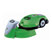
E. Insert the pop rivet to the special tool and place the end of the pop rivet into the hole in the
Thermistor, as illustrated in Figure 4.2.11.3 below.
Figure 4.2.11.3
Preparing the Thermistor
for assembly