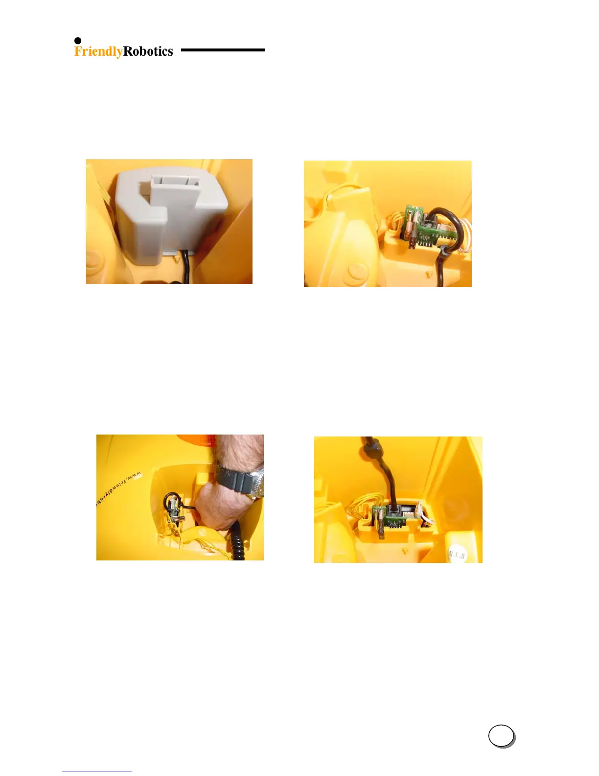
E. Squeeze the two tabs of the fuse cover, while pulling up the fuse cover (Figure 4.1.3.3).
F. To replace the M. Controller holder assembly, disconnect the yellow charging cable from
the Connector Board (3 pins). Replace the defective M. Controller holder assembly with a new
one and repeat previous steps in reverse order, ensuring correct routing of wires, as illustrated
in Figure 4.1.3.4.
Figure 4.1.3.3 Figure 4.1.3.4
Releasing the fuse cover Correct routing of wires
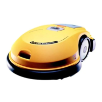
G. To replace the Manual Controller, release the cable’s strain release and the plug from
the socket by squeezing the latch, as illustrated in Figures 4.1.3.5 and 4.1.3.6.
H. Replace the defective Manual Controller with a new one and repeat previous steps
in reverse order, ensuring correct routing of wires, as illustrated in Figure 4.1.3.4 above.
I. Complete the General Test as outlined in section 5.1
Figure 4.1.3.5 Figure 4.1.3.6
Releasing the cable’s strain release and connection to the Connector Board
4
5