6 Using the device
6.1
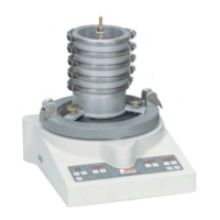
Sieving with the ANALYSETTE 3
6.1.1 Fing and clamping the sieves
On the vibratory plate, it is possible to t up to
‐ 10 sie
ves with a height of 50 mm (or 2") or
‐ 16 sieves with a height of 25 mm (or 1")
between the sieve pan (collecng vessel) and clamping
lid. The combinaon of sieves and sieve pan is called a
sieve set.
Make sure not to clamp more than 6 kg on the ANALY‐
SETTE 3 (sieve set + sieving stock).
1. The sie
ves are placed onto the sieve pan (with increasingly larger
mesh widths, i.e. nest sieve at the boom) and loosely inserted
into one another with seal rings unl the sieve set is complete.
NOTICE!
The sie
ve mesh width must increase from the
boom to the top. Informaon on the appro-
priate order for staggering the sieve mesh widths
and on conducng a sieve analysis can be
obtained from:
– the DIN 66 165 standard, Parts 1 and 2,
– the AUTOSIEVE program and / or
– our laboratory for technical applicaons.
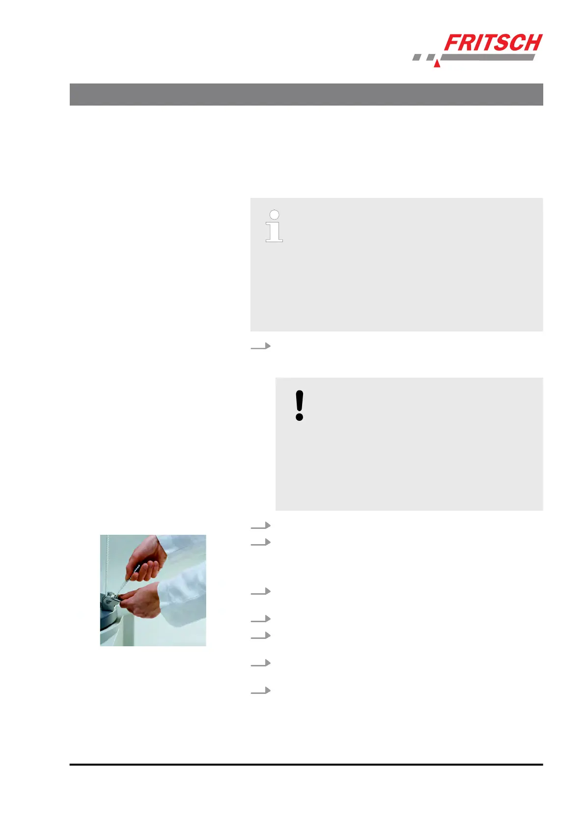
2. Unscr
ew the knurled knob on the toothed belt as far as possible.
3. Mo
ve the clamping lever on the belt clamping device downwards
and insert the toothed belt through the holder from the inside to
the outside. The teeth of the toothed belt interlock with the teeth
of the belt clamping device.
4. Place the sie
ve set with the sieve pan centrally on the rubber pad
of the vibratory plate.
5. Place the sie
ving stock into the top sieve.
6. Fit the clamping lid so tha
t the inner rubber surface seals the sieve
edge.
7. Aach the knurled knob with the tension belt ng to the
clamping lid.
8. Ligh
tly pull the toothed belt ght and move it upwards unl its
teeth interlock with the teeth of the belt clamping device.
Using the device
- 23 -