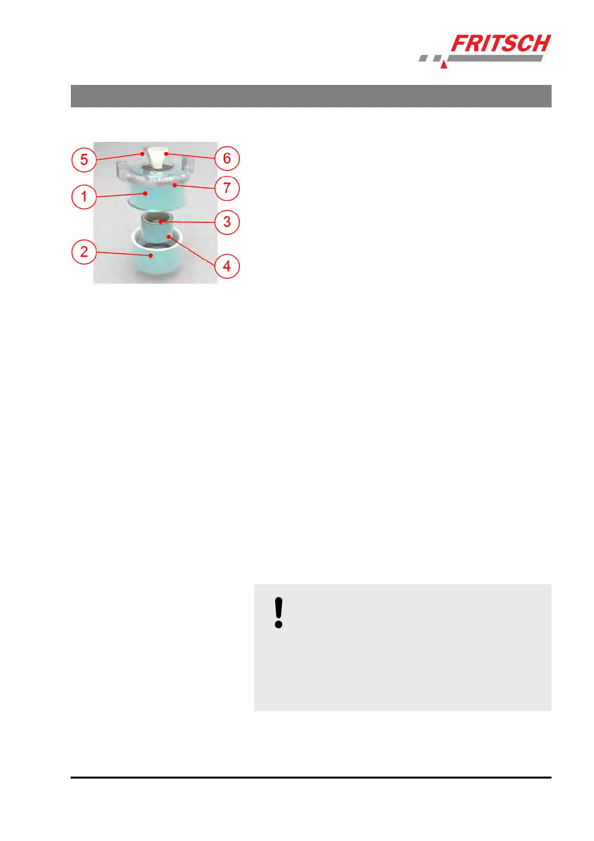
1 Upper part
2 Lower part
3 Grinding ball 50 mm
4 Mortar
5 Bent tube venlaon
6 Funnel for liquid nitrogen
7 Amplitude display
The lower part (2) is placed on the vibratory plate and the mortar with
ball (3) and grinding s
tock is placed into the plasc surround. Then the
upper part (1) is placed on the lower part, so that the seal ring in the
upper part is resng on the mortar edge and the bent venlaon tube
(5) is facing backwards and the amplitude display (7) is facing forwards.
The device is then clamped like a normal sieve set.
Liquid nitrogen is then poured in carefully through the funnel (6); it evap-
orates immediately and escapes through the bent venlaon tube. The
boiling nitrogen can be observed through the transparent Makrolon
screen. Nitrogen is added unl the amount of vapour escaping
decreases. The grinding elements can then be cooled down enough for
grinding to begin. The same must be observed as for normal grinding
with the PULVERISETTE 0 as described above. (See
Ä
Chapter 7.5.1.1
„Fing and clamping the mortar“ on page 39).
During grinding, rell the same amount of nitrogen that evaporates.
7.5.1.4 Final neness of a grinding process with the PULVERISETTE 0
The achievable nal neness (PULVERISETTE 0) of the grinding stock is
approx. 10 µm. (Depending on the grindability of the sample and the
grinding duraon)
7.5.1.5 Cleaning grinding elements
Clean the mortar bowl and grinding balls aer every use; e.g. under run-
ning water using a brush and a commercially available cleaning agent.
Cleaning with an ultrasonic cleaner is permied.
NOTICE!
Cool grinding elemen
ts made of agate, sintered
corundum and zirconium oxide slowly and carefully.
Do not heat agate elements in a microwave under any
circumstances (heang is too fast).
They must never be exposed to thermal shocks as this
could cause irreparable damage to the parts ® They
will burst apart like in an explosion.
Accessories
- 41 -