Boiler Installation
Boiler Assembly
Froling GmbH, Industriestrasse 12, A-4710 Grieskirchen, Austria Page 23
www.froling.com M1060008_US
3.5 Installing the FHG
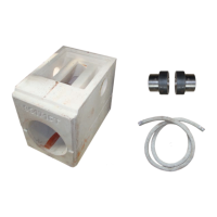
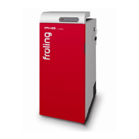
3.5.1 Installing the flue gas pipe nozzle
Place the ceramic fiber gasket in
position
Position the flue gas pipe nozzle and
attach it using the pre-installed
spacer washers and nuts
Caution: ½" sleeve must point to the
left as viewed from the rear of the
boiler.
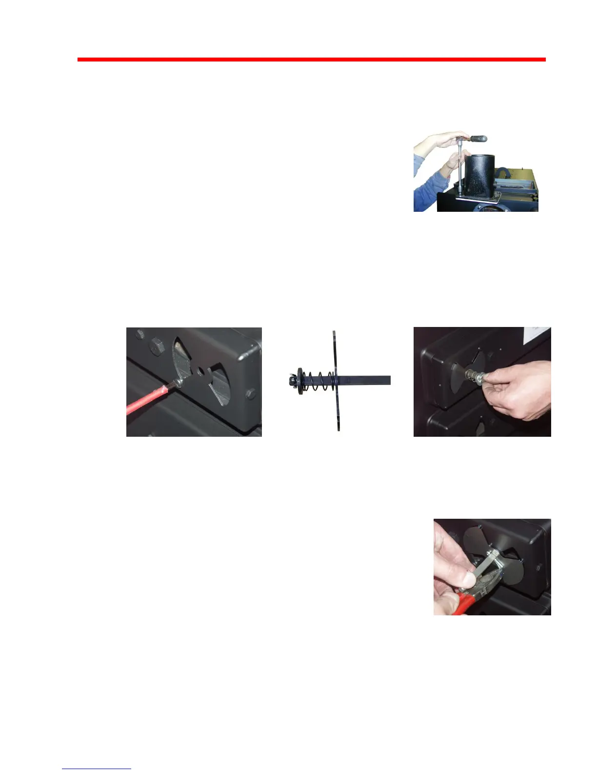
3.5.2 Install the pneumatic rods for the primary and secondary air
For both pneumatic rods:
Remove the split pin opposite the spring and pull off one of the air
flaps.
Right-hand actuators
The hex head bolt (1) in the above picture must be used on the other
side.
Unscrew the stop screws on the right-hand side of the boiler far
enough to allow the air flap to make contact with the thread.
Insert the pneumatic rod at the left-hand side of the boiler
The flap with the spring (2) must be at the left-hand air duct.
Position the flaps on the opposite side
Caution: Install the flaps in the same
position.
Secure the flaps with the split pins