Boiler Control System Lambdatronic S 3200
Froling GmbH, Industriestrasse 12, A-4710 Grieskirchen, Austria Page 55
www.froling.com M1060008_US
5.7 Menu – Manual
Use this section to verify the proper function of components connected
to the digital and analog outputs. This is important before initial start-
up. It is also used to activate Lamda probe for proper calibration.
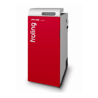
5.7.1 Digital Outputs
This menu is used to test the digital outputs by service technicians
only! The parameters displayed vary depending on the configuration.
In Automatic mode the state of the output signal can be supervised:
A ... Automatic - A 0 ... Automatic, OFF
- A 1 ... Automatic, ON
In Manual mode the output signals can be forced ON or OFF:
0 ... Manual, OFF
1 ... Manual, ON
Heating circuit pump 0 A 0
Primary air flap OPEN A 0
Primary air flap CLOSE A 0
Secondary air flap OPEN A 0
Secondary air flap CLOSE A 0
Primary air Actual value: 0%
A 0%
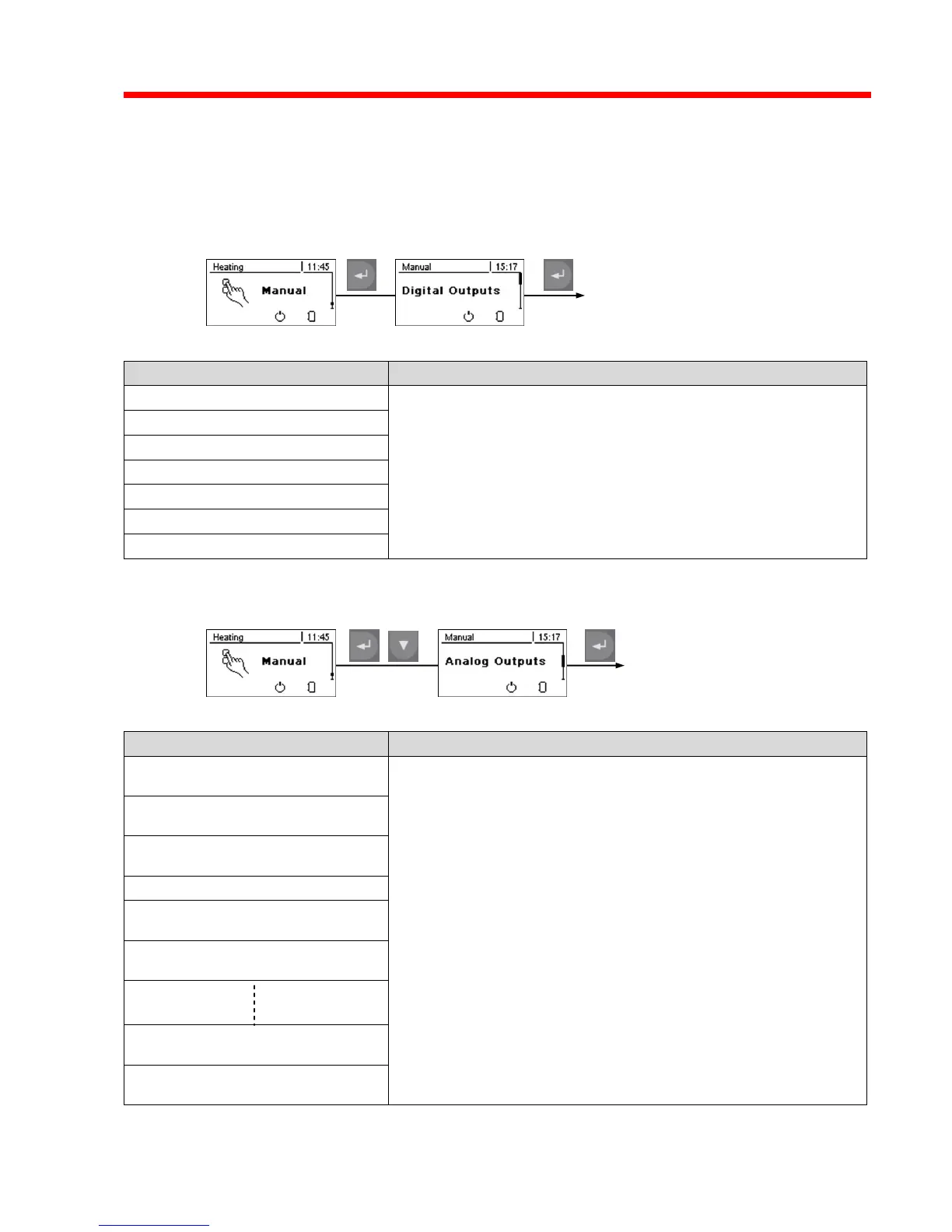
This menu is used to test the analog outputs by service technicians
only! The parameters displayed vary depending on the configuration.
In Automatic mode the state of the output signal can be supervised:
A ... Automatic - A 0% ... Automatic, OFF
- A 1%-100% ... Automatic, ON at % value
In Manual mode the output signals can be forced to an user-defined
value:
0% ... Manual, OFF
1%-100% ... Manual, ON at % user-defined value
ID Fan = Induced Draft Fan
Pump 1 on core module = Thermal Storage System circulator
All other pump outputs (circulators): not used
Secondary air Actual value: 0%
A 0%
ID Fan Actual value: 0%
A 0%
Pump 1 on core module A 0%
Pump 1 at hydraulic module
address 0 A 0%
Pump 2 at hydraulic module
address 0 A 0%
Pump 1 at hydraulic module
address 7 A 0%
Pump 2 at hydraulic module
address 7 A 0%