2 | Power connection and wiring
24 B1820023_en | Service handbook Lambdatronic H 3200 - T4e
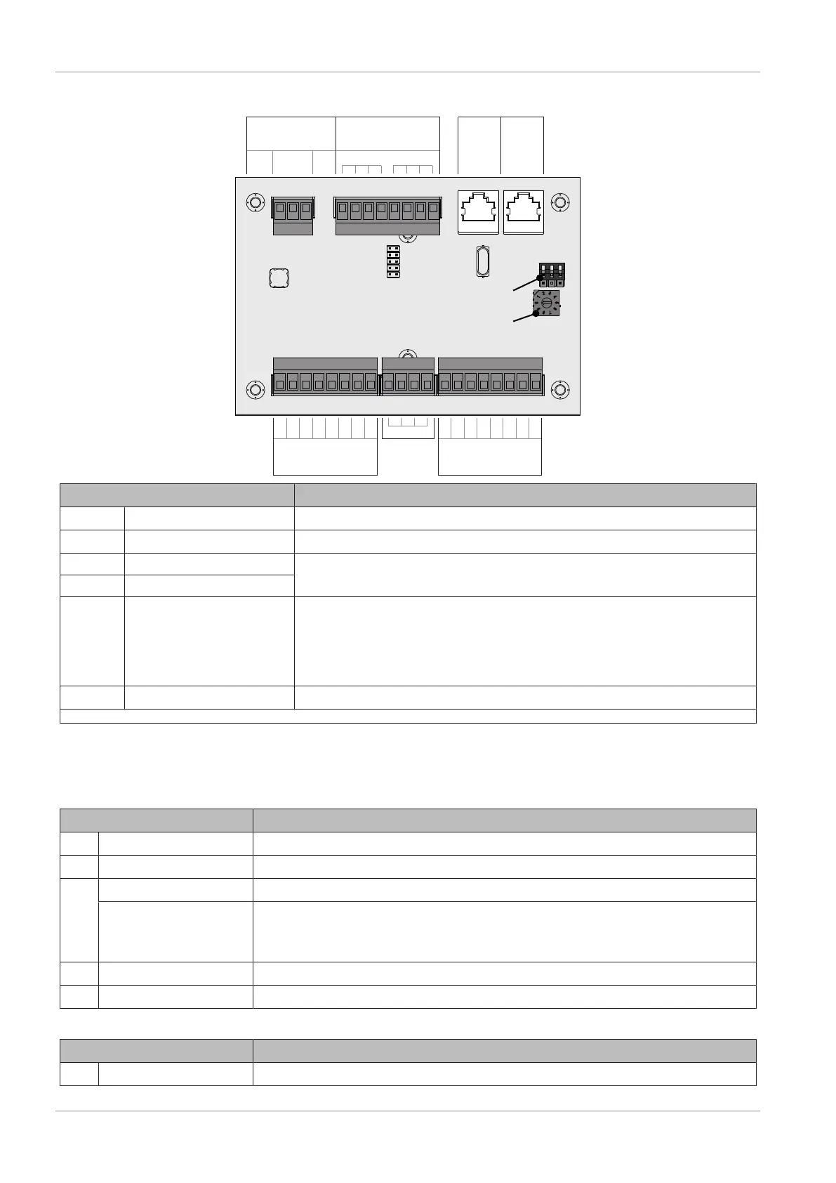
2.2.6 Analogue module
FRANA12
8 7 6 5 4 3 2
GND
1 8 7 6 5 4 3 2 1
AN-01
(Eingänge)
AN-02
(Ausgänge)
GND+24V
- + S
AN-03
(Bus)
AN-04
(Bus)
AN-06
(Thermoelement)
AN-05
(Versorgung)
Analogue module
Module address
End jumper
Connection / Name Note
AN-01 Inputs 1…8
Connection cable
1)
1 x 0.75 mm²
AN-02 Outputs 1…8
Connection cable
1)
1 x 0.75 mm²
AN-03 Bus
CAT 5 patch cable grey RJ45 SFTP 1:1 configuration
AN-04 Bus
AN-05 Power supply
24 V power supply of the module, connection cable
1)
2 x 1.0 mm²
- Pellet boiler: 24 V power supply
- pellet boiler and dual fuel boiler: Gravity shaft, terminal PM-12 or PM-13 at the
pellet module
- wood chip boiler: Supply via 24 V power supply unit
AN-06 Thermocouple
Use sensor connection
1. YMM to ÖVE-K41-5 or H05VV-F to DIN VDE 0881-5
NOTICE!The inputs and output are pre-configured, so it is essential the following addressing is
complied with.
Standard configuration – Analogue module with address 0
Input Designation
1
Actual voltage HV module 1
2
Actual current HV module 1
3
Actual voltage HV module 2
External power specification (0-10V)
On T4e with 2 HV modules, a different input must be used to use the external power
specification. The input is set in the “Boiler – General settings” menu accordingly.
4
Actual current HV module 2
5 T4e 300/350
Position feedback of primary air flap
Output Designation
1
Target voltage HV module 1