Power connection and wiring | 2
B1820023_en | Service handbook Lambdatronic H 3200 - T4e 27
Input Designation
7
Gravity shaft (coupled)
Output Designation
1
Screw 1 forward
2
Screw 1 backwards
:
4
Screw 2 forward
5
Screw 2 backwards
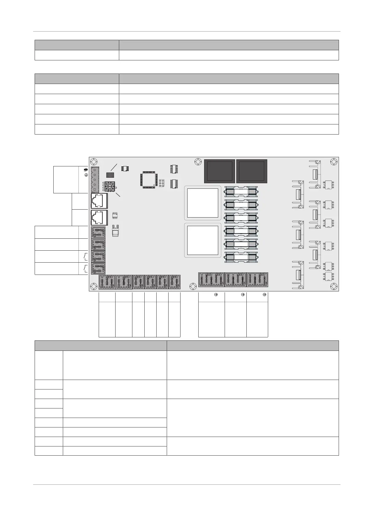
2.2.8 Feed system module
AU-08 (Sensor 2)
AU-09 (Sensor 1)
AU-10 (Fallschacht-
deckel 2)
AU-11 (Fallschacht-
deckel 1)
AU-12 (Verriegelung
Eingang)
AU-13 (Externe
Freigabe)
AU-14 (Netz)
AU-15 (Ausgang 2)
AU-16 (Ausgang 1)
(FRAUM 10)
CAN L
CAN H
+U
Bu
s
GND
+24V
GND
+24V
GND
+24V
IN
GND
+24V
IN
+24V
IN
+24V
IN
+24V
IN
+24V
IN
L1
N
L2
L3
L1
L2
L3
L1
L2
L3
F1 (17)
F2 (18)
F3 (19)
F4 (20)
F5 (21)
F6 (22)
AU-01
(Bus)
AU-02
(Bus)
AU-03
(Bus)
AU-04
(Versorgung 24V)
AU-05
(Versorgung 24V)
AU-06
(Verriegelung Ausgang 2)
AU-07
(Verriegelung Ausgang 1)
End jumper
Module address
Feed system module
Connection / Name Note
AU-01 Bus
Port with cable – LICY paired 2x2x0.5;
Ü "Connecting the bus cable" [}29]
r Caution! CAN L and CAN H must not be connected to +U
BUS
!
AU-02 Bus
Patch cable CAT 5 RJ45 SFTP 1:1 configuration
AU-03
AU-04 24V power supply
Connection cable
1)
2 x 0.75 mm
2
AU-05
AU-06 Output 2 latch
AU-07 Lock output 1
AU-08 Sensor 2
Connection cable
1)
3 x 0.75 mm
2
, N/O switch contact 254V (e.g.
connecting a light barrier)
AU-09 Sensor 1