(9) Mains cable
(10) LED strip option.
Lights up in the appropriate colors depending on the state of charge, according to
the indicators explained in the "Control panel" section.
(11) Control panel
(12) Connection area for options
The connection area is only accessible by removing the connection plate on the
front of the device.
To do this, follow the warnings in the "Safety" section of the "Options" chapter.
17 G / 2 13V / 1
Y / 3 R / 4
B Dete
C2 G
C1 G 13V O
C1 L C2 L
C1 H C2 H
- St + St
Pin Pin
Plug
Code
Plug
Code
Plug
18p
15
13
11
9
7
5
3
1
18
16
14
12
10
8
6
4
2
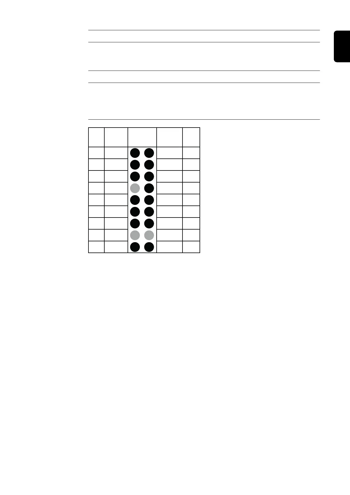
Connections for 18-pin optional plug on
the P-Control PCB inside the housing
21
EN-US