8.4 Terminal Specifications
8-13
Chap. 8 SPECIFICATIONS
Classifi-
cation
Symbol Name Functions
Related
function
codes
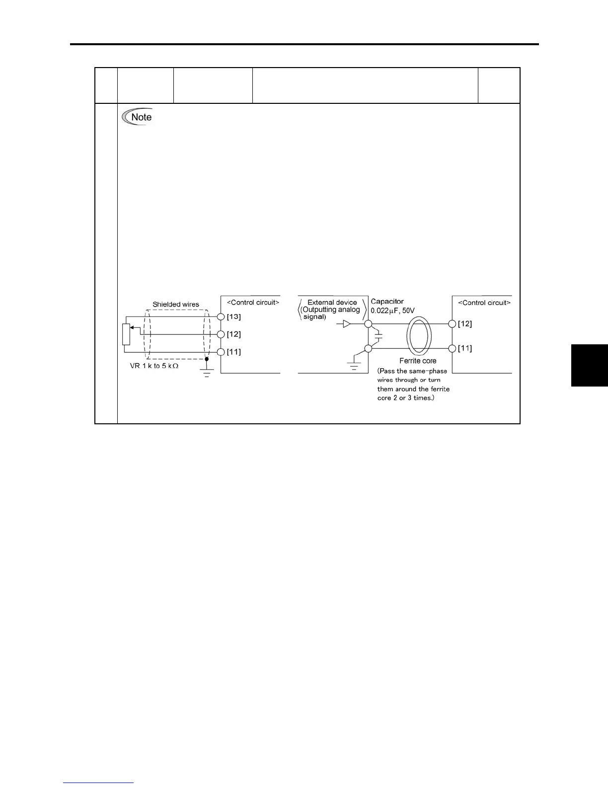
• Since weak analog signals are handled, these signals are especially susceptible to the
external noise effects. Route the wiring as short as possible (within 66 ft (20 m)) and
use shielded wires. In principle, ground the shielding layer of the shielded wires; if
effects of external inductive noises are considerable, connection to terminal [11] may
be effective. As shown in Figure 8.1, ground the single end of the shield to enhance the
shielding effect.
• Use a twin contact relay for weak signals if the relay is used in the control circuit. Do
not connect the relay's contact to terminal [11].
• When the inverter is connected to an external device outputting the analog signal, a
malfunction may be caused by electric noise generated by the inverter. If this happens,
according to the circumstances, connect a ferrite core (a toroidal core or an equivalent)
to the device outputting the analog signal and/or connect a capacitor having the good
cut-off characteristics for high frequency between control signal wires as shown in
Figure 8.2.
• Do not apply a voltage of +7.5 VDC or higher to terminal [C1]. Doing so could damage
the internal control circuit.
Analog input
Figure 8.1 Connection of Shielded Wire Figure 8.2 Example of Electric Noise Prevention

 Loading...


