8.4 Terminal Specifications
8-19
Chap. 8 SPECIFICATIONS
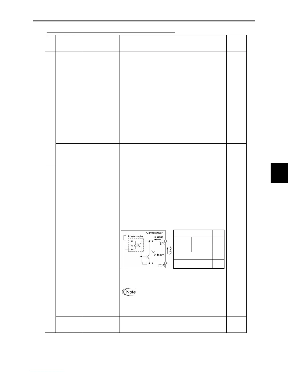
Item Max.
ON level 2V
Operation
voltage
OFF level 27V
Maximum load current at ON
50mA
Leakage current at OFF
0.1mA
Analog output, transistor output, and relay output terminals
Classifi-
cation
Symbol Name Functions
Related
function
codes
[FMA] Analog monitor
The monitor signal for analog DC voltage (0 to +10
VDC) is output. The signal functions can be selected
with the function code
F31 from the following.
• Output frequency (before slip compensation)
• Output frequency (after slip compensation)
• Output current • Output voltage
• Input power • PID feedback value
• DC link bus voltage
• Analog output test (+)
(Output voltage: 0 to +10 VDC,
maximum current: 2 mA
Up to two analog voltmeters can be connected.)
F30, F31
Analog output
[11] Analog common Common for analog output signal ([FMA])
This terminal is electrically isolated from terminals
[CM] and [Y1E].
Commands listed below can be assigned to terminal
[Y1] and the signal is output according to the
command.
Normal/negative logic output switching feature:
Switches the logic value (1/0) for ON/OFF of the
terminals between [Y1] and [Y1E]. If the logic value
for ON between [Y1] and [Y1E] is 1 in the normal
logic system, for example, OFF is 1 in the negative
logic system.
Digital output circuit specification
Figure 8.5 shows examples of connection between the
control circuit and a PLC.
E20
[Y1] Transistor output
• Check the polarity of an external power
input.
• To connect a control relay, connect a
surge absorbing diode across the coil of
the relay.
Transistor output
[Y1E]
Transistor output
common
Common for transistor output signal
(Isolated from terminals [CM] and [11].)

 Loading...


