Connecting Programmable Controller (PLC) to Terminal [Y1]
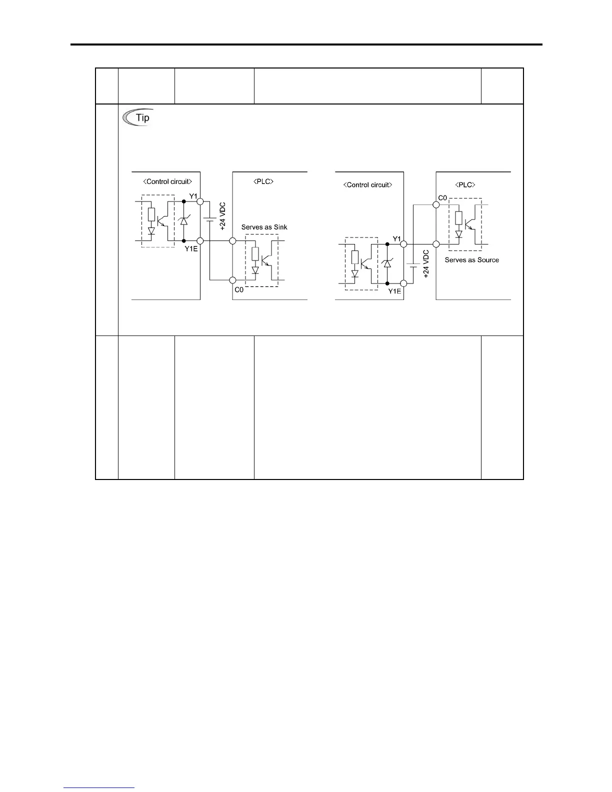
Figure 8.5 shows two examples of circuit connection between the transistor output of the
inverter’s control circuit and a PLC. In example (a), the input circuit of the PLC serves as
the sink for the control circuit, whereas in example (b), it serves as the source for the
control circuit.
Transistor output
(a) PLC serving as Sink (b) PLC serving as Source
Figure 8.5 Connecting PLC to Control Circuit
Relay output
[30A],
[30B],
[30C]
Alarm relay
output (for any
fault)
(1) Outputs a contact signal (SPDT) when a
protective function is activated to stop the motor.
Contact rating: 250 VAC 0.3A cosI = 0.3
+48 VDC, 0.5A
(2) Possible to select a command similar to terminal
[Y1] for transistor output signal and use it for
signal output.
(3) The normal/negative logic output changeover is
applicable to these contact outputs: "Terminals
[30A] and [30C] are short-circuited for ON signal
output" or "terminals [30B] and [30C] are
short-circuited (non-excite) for ON signal output"
E27

 Loading...


