9-2
The following tables list the function codes available for the FRENIC-Mini series of inverters.
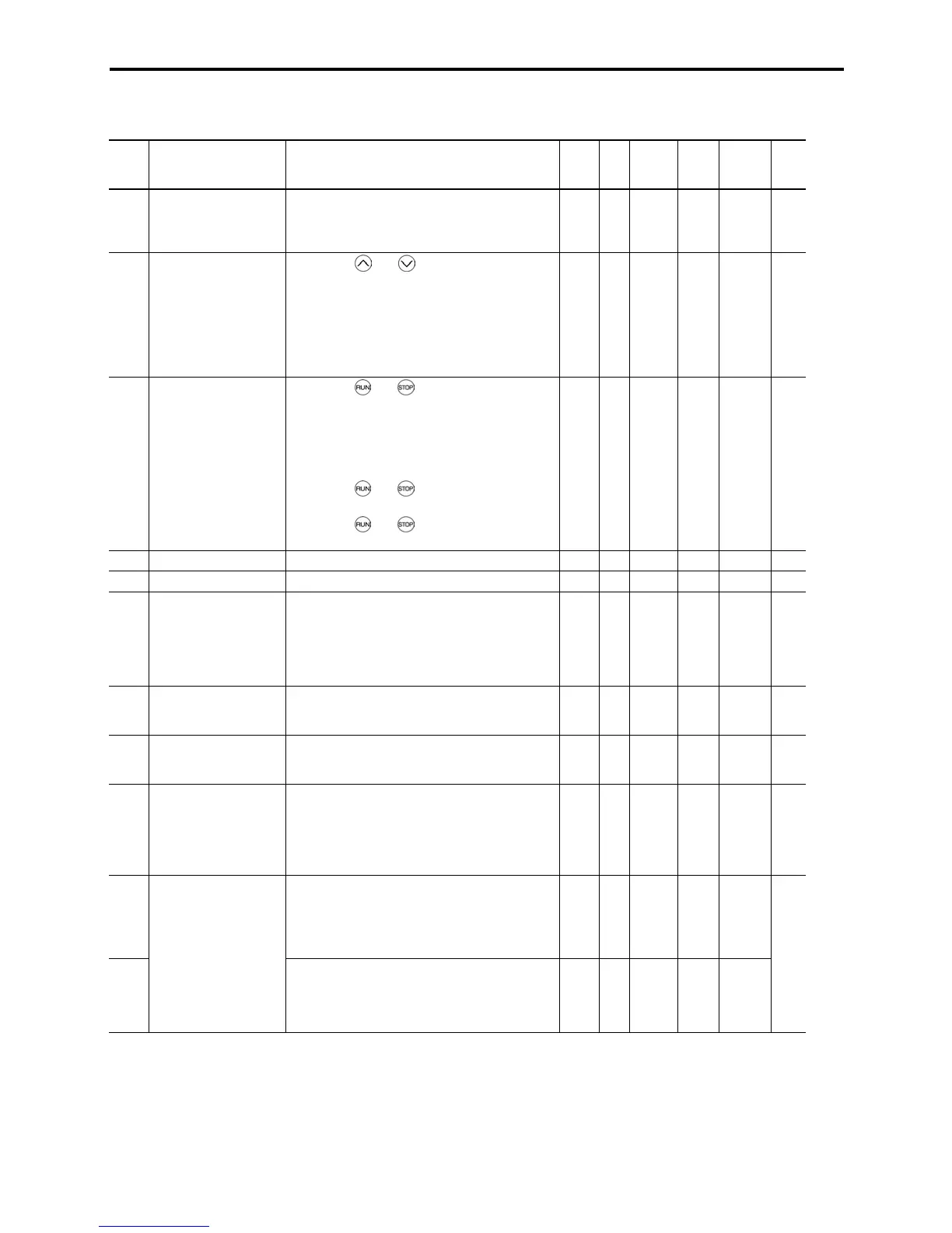
F codes: Fundamental Functions
Code Name Data setting range
Incre-
ment
Unit
Change
when
running
Data
copy
Default
setting
Refer
to:
F00 Data Protection 0: Disable data protection
(Function code data can be edited.)
1: Enable data protection
(Function code data cannot be edited.)
— — Y N 0 9-12
F01 Frequency Command 1
0: Enable
and keys on the built-in
keypad
1: Enable the voltage input to terminal [12]
2: Enable the current input to terminal [C1]
3: Enable the sum of voltage and current inputs
to terminals [12] and [C1]
4: Enable the built-in potentiometer (POT)
— — N Y 4 9-12
F02
Running/Stopping and
Rotational Direction
0: Enable
and keys on the built-in
keypad to run and stop motor
(The (FWD) or (REV) command should be
ON for forward or reverse rotation.)
1: Enable the external signal command (FWD)
or (REV) command to run motor
2: Enable
and keys on the built-in
keypad to run/stop motor forward
3: Enable
and keys on the built-in
keypad to run/stop motor reverse
— — N Y 2 9-13
F03 Maximum Frequency 25.0 to 400.0 0.1 Hz N Y 60.0 9-14
F04 Base Frequency 25.0 to 400.0 0.1 Hz N Y 60.0 9-15
F05 Rated Voltage (at Base
Frequency)
0: Output a voltage in line with
variance in input voltage
80 to 240: Output a voltage AVR-controlled *
2
(Note 1)
160 to 500: Output a voltage AVR-controlled *
2
(Note 2)
1 V N Y2 230
460
9-15
F07 Acceleration Time 1 0.00 to 3600
Note: Acceleration time is ignored at 0.00.
(External gradual acceleration pattern)
0.01 s Y Y 6.00 9-17
F08 Deceleration Time 1 0.00 to 3600
Note: Deceleration time is ignored at 0.00.
(External gradual deceleration pattern)
0.01 s Y Y 6.00 9-17
F09 Torque Boost 0.0 to 20.0
(The set voltage at base frequency for F05 is
100%.)
Note: This setting is effective for auto torque
boost/auto energy saving operations specified
by function code F37 (= 0, 1, 3, or 4).
0.1 % Y Y Fuji's *
1
standard
torque
boost
9-17
F10 Electronic Thermal
Overload for Motor
Protection
(Select motor
characteristics)
1: For general-purpose motors with built-in
self-cooling fan
2: For inverter-driven motors or high-speed
motors with forced-ventilation fan
— — Y Y 1
F11 (Overload detection
level)
0.00 (Disable)
1 to 135% of rated current (allowable continuos
load current) of the inverter
0.01 A Y Y
1
Y2
Nominal
*
1
rated
current of
Fuji
standard
motor
9-18
*
1
"Fuji's standard torque boost," "Nominal rated current of Fuji standard motor," and "Nominal rated capacity of Fuji standard motor" differ
depending upon the rated input voltage and rated capacity. Refer to Table 9.1 "Fuji Standard Motor Parameters" on page 9-11.
*
2
AVR: Automatic Voltage Regulator
(Note 1) For the three-phase 230 V and single-phase 230 V
(Note 2) For the three-phase 460 V

 Loading...


