9.1 Function Code Tables
9-3
Chap. 9 FUNCTION CODES
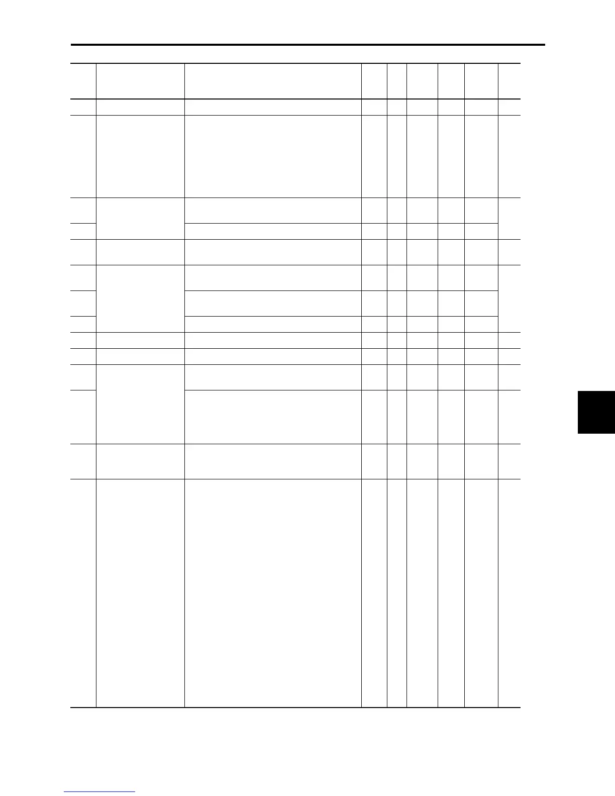
Code Name Data setting range
Incre-
ment
Unit
Change
when
running
Data
copy
Default
setting
Refer
to:
F12 (
Thermal time constant
) 0.5 to 75.0 0.1 min Y Y 5.0 9-18
F14 Restart Mode after
Instantaneous Power
Failure
0: Disable (Trip immediately without restart)
1: Disable (Trip without restart after recovery of
power)
4: Enable (Restart at the frequency at which
the power failure occurred, for general load)
5: Enable (Restart at the start frequency, for
low-inertia load)
— — Y Y 0 9-19
F15 Frequency Limiter
(High)
0.0 to 400.0 0.1 Hz Y Y 70.0
F16 (Low) 0.0 to 400.0 0.1 Hz Y Y 0.0
9-21
F18 Bias (for frequency
command 1)
-100.00 to 100.00 0.01 % Y* Y 0.00 9-22
F20 DC Braking
(Start frequency)
0.0 to 60.0 0.1 Hz Y Y 0.0
F21 (Braking level) 0 to 100 (Rated output current of the inverter
interpreted as 100%.)
1 % Y Y 0
F22 (Braking time) 0.00 (Disable), 0.01 to 30.00 0.01 s Y Y 0.00
9-23
F23 Start Frequency 0.1 to 60.0 0.1 Hz Y Y 1.0 9-25
F25 Stop Frequency 0.1 to 60.0 0.1 Hz Y Y 0.2 9-25
F26 Motor Sound
(Carrier frequency)
0.75 to 15 1 kHz Y Y 2 9-25
F27 (Tone) 0: Level 0
1: Level 1
2: Level 2
3: Level 3
— — Y Y 0 9-26
F30 Terminal [FMA]
(Gain to output voltage)
0 to 200
If 100 is set, +10 VDC will be output from [FMA]
at full scale.
1 % Y* Y 100 9-26
F31 Analog Output Signal
Selection for [FMA]
(Monitor object)
0: Output frequency 1
(before slip compensation)
Maximum output frequency at full scale
1: Output frequency 2
(after slip compensation)
Maximum output frequency at full scale
2: Output current
Two times the inverter's rated output
current at full scale
3: Output voltage
250 V (500 V) at full scale
6: Input power
Two times the inverter's rated output
capacity at full scale
7: PID feedback value
Feedback value is 100% at full scale
9: DC link bus voltage
500 VDC (for 230 V),1000 VDC (for 460 V)
at full scale
14: Test analog output (+) voltage
If F30 = 100, +10 VDC at full scale
— — Y Y 0 9-26

 Loading...


