9-14
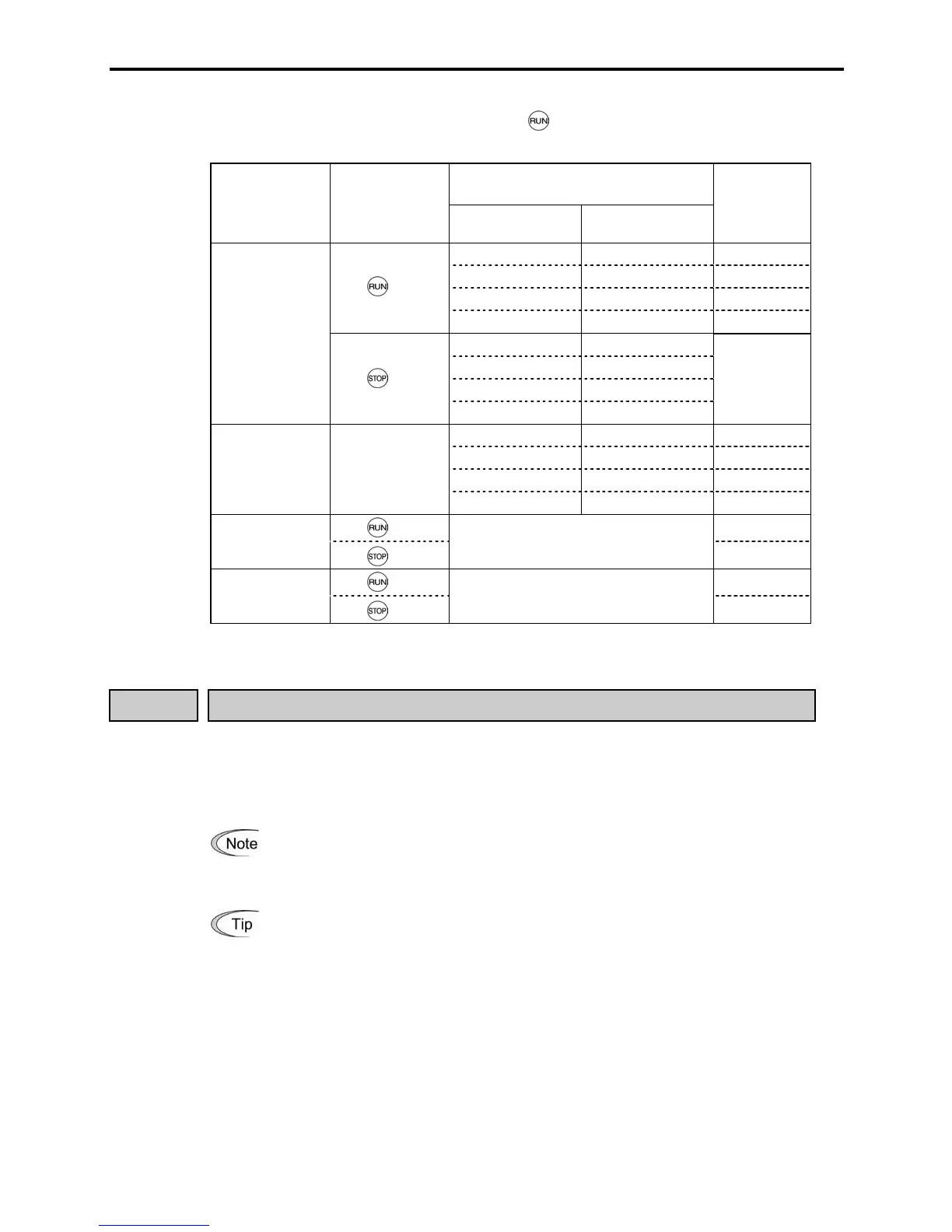
The table below lists the operational relationship between function code F02
(Running/stopping and rotational direction), the key operation, and control signal inputs to
terminals [FWD] and [REV], which determines the rotational direction.
Control Signal Inputs to
Terminals [FWD] and [REV]
Data for F02
Key on the
built-in keypad
Function code E98
(FWD) command
Function code E99
(REV) command
Motor
rotational
direction
OFF OFF Stop
ON OFF Forward
OFF ON Reverse
key
ON ON Stop
OFF OFF
ON OFF
OFF ON
0
key
ON ON
Stop
OFF OFF Stop
ON OFF Forward
OFF ON Reverse
1 Ignored.
ON ON Stop
key
Forward
2
(forward/fixed)
key
Ignored.
Stop
key
Reverse
3
(reverse/fixed)
key
Ignored.
Stop
F03 Maximum Frequency
Sets the maximum frequency to drive the motor. Setting the frequency out of the range rated for
the equipment driven by the inverter may cause damage or a dangerous situation. Set a
maximum frequency appropriate for the equipment.
- Data setting range: 25.0 to 400.0 (Hz)
In general, internal impedance of high-speed motors is low. This may cause
unstable motor/inverter behavior. When this kind of motor is used, it is
recommended that the carrier frequency (F26) be set to 15 kHz and the
motor/inverter operation be checked.
Keep the ratio between base frequency (F04) and maximum frequency to 1:8 o

 Loading...


