9-28
F43 Current Limiter (Operation condition)
F44 Current Limiter (Limiting level)
F43 enables or disables the current limiter. If it is enabled, the inverter controls the output
frequency while keeping the current set to F44 in order to prevent the motor from stalling.
With F43, you may select whether the current limiter works during constant speed operation
only (F43 = 1) or during both acceleration and constant speed operation (F43 = 2). Set F43 to 1,
for example, to drive the motor at maximum performance in the acceleration zone and to limit
the drive current in the constant speed zone.
Operation condition (F43)㩷
Select the motor running state in which the current limiter will work.
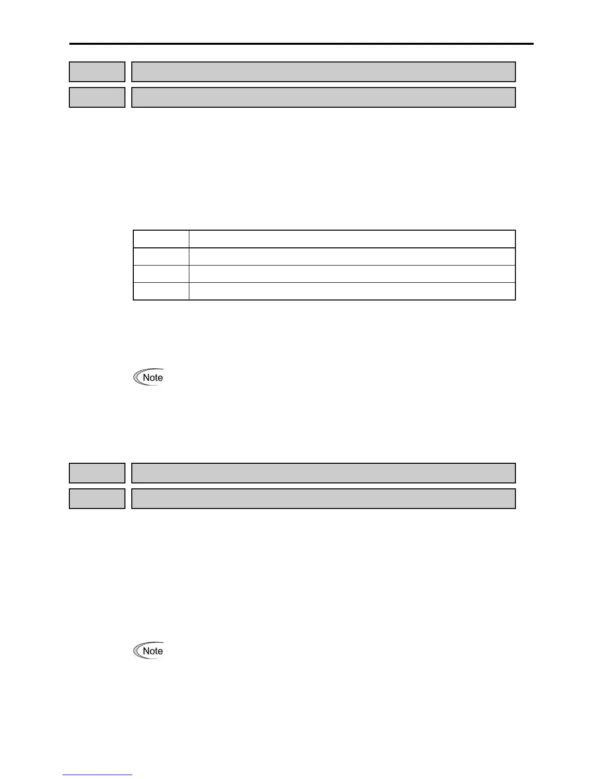
Data for F43 Function
0 Disable (No current limiter works.)
1 Enable the current limiter during constant speed operation
2 Enable the current limiter during acceleration and constant speed operation
Limiting level (F44)㩷
Select the level at which the current limiter will work.
- Data setting range: 20 to 200% (Percentage ratio of rated current of the inverter)
• The current limiting feature selected by F43 and F44 are implemented by
software, so an operational delay may occur. To avoid the delay, use the current
limiter (hardware) simultaneously (H12 = 1).
• If an overload is applied when the limiting level is set extremely low, the inverter
will immediately lower its output frequency. This may cause an overvoltage trip
or dangerous turnover of the motor rotation due to undershooting.
F50 Electronic Thermal Overload Relay (Discharging capability)
F51 Electronic Thermal Overload Relay (Allowable loss)
These function codes configure the electronic thermal overload relay to protect the braking
resistor from overheating.
Set the discharging capability and allowable average loss of braking resistors to F50 and F51,
respectively. Those values differ depending upon the specifications of the braking resistor.
Refer to the tables on the next page.
For built-in braking resistors, you may set 0 and 0.000 to F50 and F51, respectively. Doing so
will automatically apply the settings given in the table on the next page.
Refer to Chapter 7, Section 7.2 "Selecting a Baking Resistor" for details.
Depending on the discharging capability margin of a braking resistor, the electronic
thermal function may operate and issue the overheat alarm "

 Loading...


