9.2 Details of Function Codes
9-29
Chap. 9 FUNCTION CODES
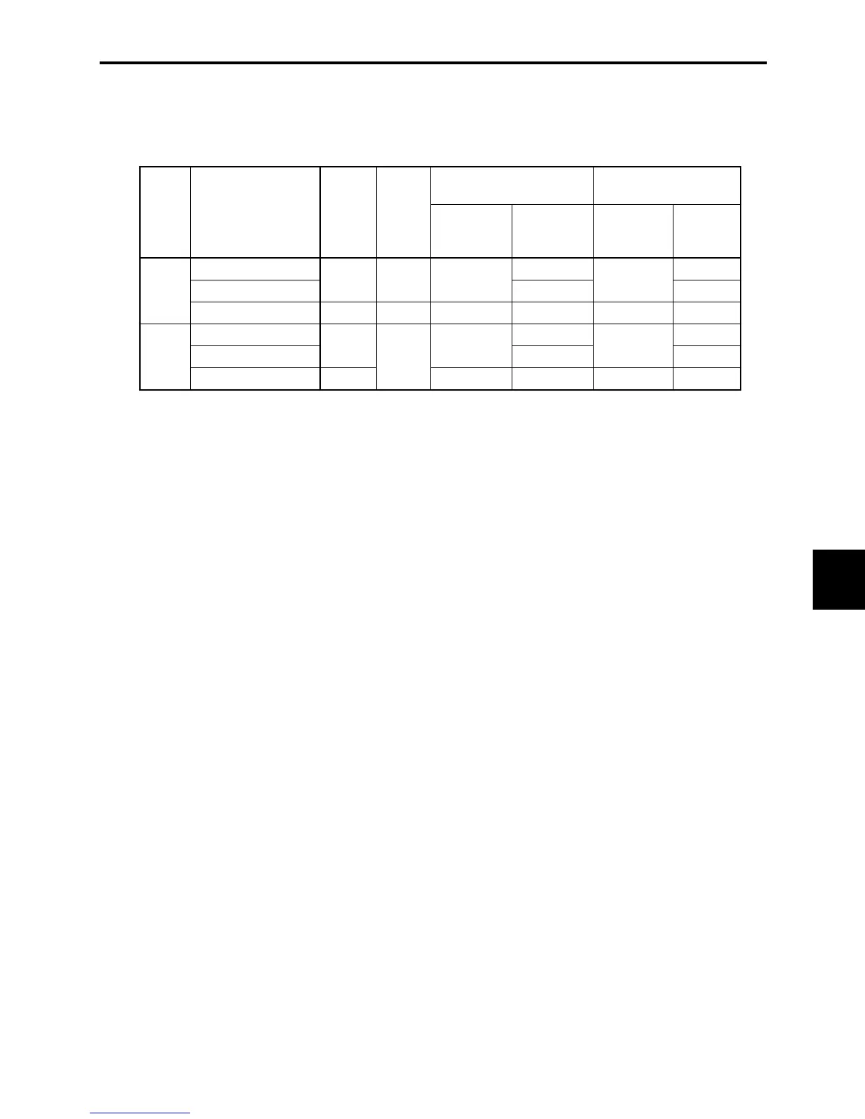
The following tables list the discharging capability and allowable average loss of the FRENIC-Mini
series of inverters. These values are determined by inverter model and specifications (built-in or external
type) of braking resistors.
Built-in braking resistor
Continuous braking
(Braking torque: 100%)
Repetitive braking
(Period: 100 sec. or less)
Power
supply
voltage
Inverter type
Resis-
tance
(:)
Ca-
pacity
(W)
Discharging
capability
(kWs)
Braking
time
(s)
Allowable
average loss
(kW)
Duty
cycle
(%ED)
FRN002C1
-2U21 18 3
FRN003C1
-2U21
60 40 14
12
0.023
2
Three-
phase
230V
FRN005C1
-2U21 40 60 15 8 0.025 1.5
FRN002C1
-4U21 18 3
FRN003C1
-4U21
240 14
12
0.023
2
Three-
phase
460V
FRN005C1
-4U21 160
40
15 8 0.025 1.5
Note 1) A box (
) in the above table replaces S or E depending on the enclosure.

 Loading...


