1.1 Features
1-3
Chap. 1 INTRODUCTION TO FRENIC-Mini
• A transistor output is provided
This enables an overload early warning, lifetime forecast or other information signals to be output during
operation.
Refer to function code E20 in Chapter 9, Section 9.2.2 "E codes (Extension terminal functions)."
• High output frequency - up to 400 Hz
The inverter can be used with equipment such as centrifugal separators that require a high motor speed. In
this case, you need to check whether the machine operation in combination with the motor is compatible or
not.
• Two points can be set for a non-linear V/f pattern.
The addition of an extra point (total: 2 points) for the non-linear V/f pattern, which can be set as desired,
improves the FRENIC-Mini's drive capability, because the V/f pattern can be adjusted to match a wider
application area.
Refer to Chapter 4, Section 4.7 "Drive Command Controller" for details.
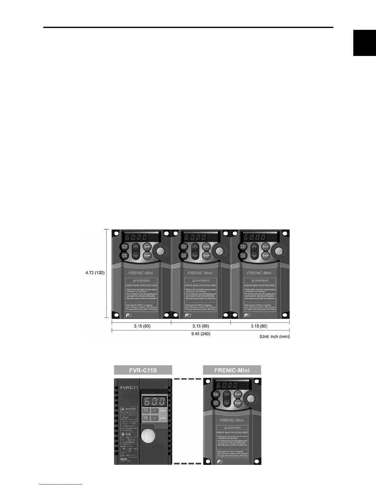
Compact size
• Side-by-side mounting
More than one FRENIC-Mini inverter can be mounted side-by-side without any gap inside your system
control panel, thereby reducing the amount of space required for installation. (Ambient temperature: 40°C
(104°F) or lower)
(Example: Inverters of 3-phase 230 V, 1 HP or less)
• External dimensions compatible with Fuji FVR-C11S series

 Loading...


