9-56
H07 Gradual Acceleration/Deceleration
Data for H07 Function
0 Disable: Linear
1 S-curve (weak)
2 S-curve (strong)
Specifies the acceleration and deceleration
patterns (output frequency patterns).
3 Curvilinear
Linear acceleration/deceleration
The inverter runs the motor with the constant acceleration and deceleration.
S-curved acceleration/deceleration
To reduce the impact on the inverter
driven motor during acceleration/
deceleration, the inverter gradually
accelerates/decelerates the motor during
both the acceleration/ deceleration
zones.
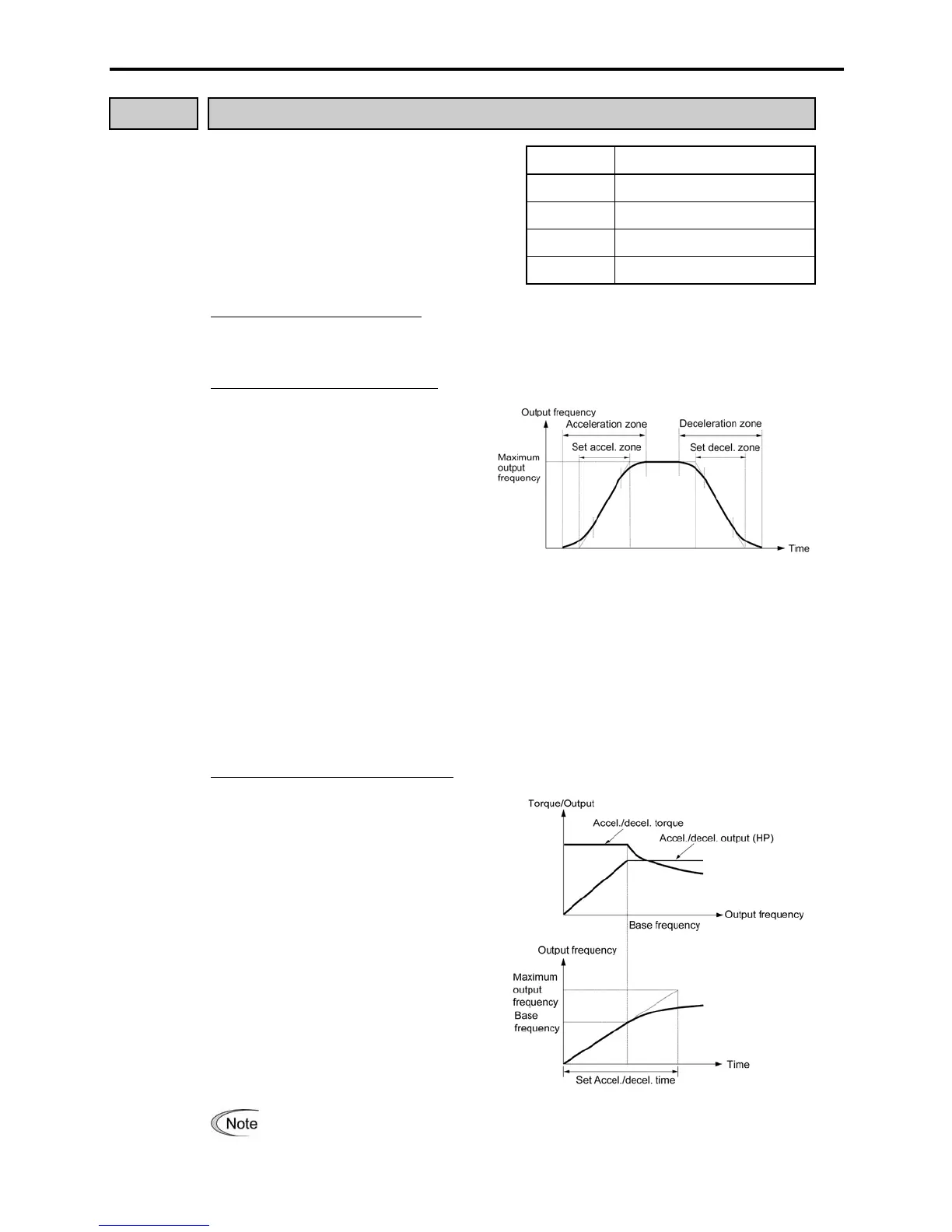
Two frequencies can be selected for
S-curved acceleration/deceleration 5%
(weak) or 10% (strong) of the maximum
output frequency. The four centers of
S-curves are not affected by this
selection. Note the set
acceleration/deceleration time defines
the linear acceleration/ deceleration in
the zones, so that the actual zone
exceeds the set zone in this case. Zones
are defined in units of time. Refer to the
figure at the right.
Curvilinear acceleration/deceleration
The inverter drives the motor to output
the maximum performance, with the
following acceleration/deceleration
pat-terns:
- In the zone under the base frequency,
linear acceleration/deceleration of
constant torque output for the motor
- In the zone above the base frequency,
speed two times the base frequency
and acceleration/deceleration half of
the base frequency
Set the acceleration/deceleration time giving due consideration to the load torque.
Refer to Chapter 7 "SELECTING OPTIMAL MOTOR AND INVERTE

 Loading...


