9.2 Details of Function Codes
9-57
Chap. 9 FUNCTION CODES
H12 Instantaneous Overcurrent Limiting
Data for H12 Function
Disable
Enable
The inverter features a hardware-controlled
output current limiter to protect it from an
overload hazard. The moment that the output
current exceeds the limited level due to
overload or other factor, the inverter controls
the output switching circuits so as to slow
down the output frequency and suppress the
output current momentarily.
This control of the switching circuits may cause an instantaneous reduction in motor output
torque. However, instantaneous torque reduction may not be allowable in some systems when
the system is in a short time overloaded state. To solve this problem, this function should be
disabled and the system set up with a proper facility that is activated by the alarm output from
the inverter when it detects an overcurrent.
The same functions to limit the output current are implemented by software as
function codes F43 and F44. Generally, software features have an operation delay,
so enable function code H12 as well.
Depending upon the load, acceleration in an extremely short period may activate
the current limiter to suppress the increase of the inverter output frequency, causing
the system oscillate (hunting) or making the inverter enter the
Alarm mode and
trip. When setting the acceleration time, therefore, you need to take into account the
load condition and moment of inertia. Refer to Chapter 7, Section 7.1, "Selecting
Motors and Inverters."
H26 Thermistor Input (Selection)
H27 Thermistor Input (Operation level)
Set these function codes to protect the motor from an overheat hazard using the PTC (Positive
Temperature Coefficient) thermistor embedded in the motor.
Thermistor (Select) (H26)
Data for H26 Function
0
Disable overheating
protection
Enables or disables overheating protection
for the motor using the PTC thermistor,
which senses motor temperature.
1
Enable overheating
protection
Thermistor (Operation Level) (H27)
Determines the operation level for the overheating protection.
- Data setting range: 0.00 to 5.00 (V)
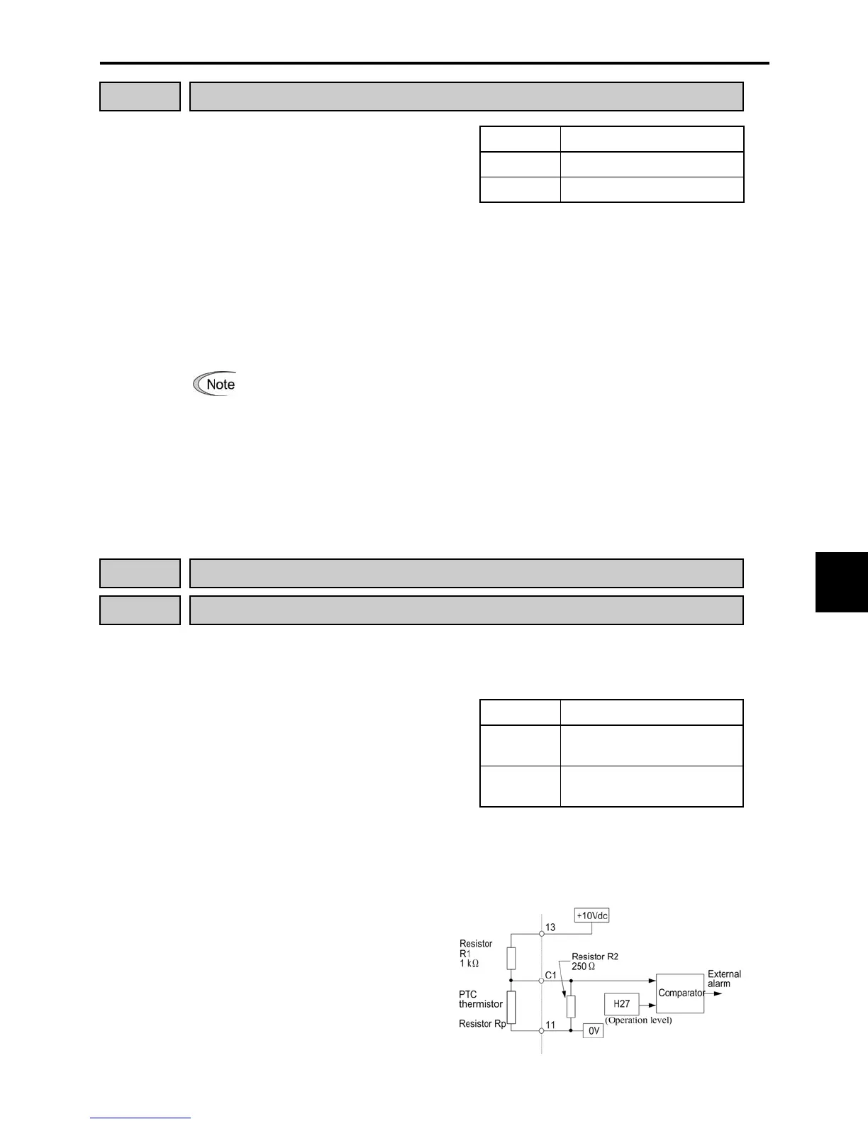
Connect the PTC thermistor as shown in
the figure at the right. The input current
from terminal [C1] flows across the
resistor R
2
and yields the voltage. If the
voltage exceeds the operation level set
by function code H27, the overheating
protection is activated, and the inverter
enters Alarm mode and issues the alarm
"

 Loading...


