3.3 Programming Mode
3-19
Chap. 3 OPERATION USING THE KEYPAD
[ 1 ] Displaying control I/O signal terminals
The I/O signal status of control circuit terminals may be displayed with ON/OFF of the LED segment or
in hexadecimal display.
Display I/O signal status with ON/OFF of the LED segment
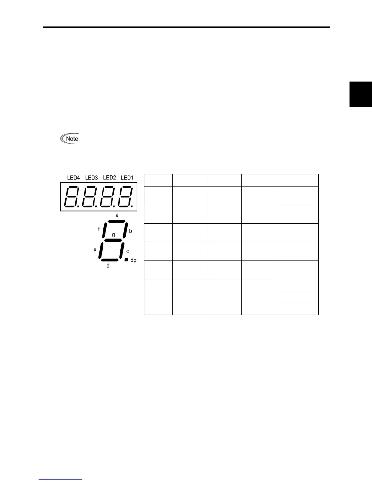
As shown in Table 3.10 and the figure below, segments "a" to "e" on LED1 light when the digital input
terminals ([FWD], [REV], [X1], [X2], and [X3]) are short-circuited (ON) with the terminal [CM] and do
not light when they are opened (OFF). Segment "a" on LED3 lights when the circuit between output
terminal [Y1] and terminal [Y1E] is closed (ON) and does not light when the circuit is open (OFF).
LED4 is for terminals [30A], [30B], [30C]. Segment "a" on LED4 lights when the circuit between
terminals [30C] and [30A] are short-circuited (ON) and does not light when they are opened.
This LED monitor displays hardware terminal information, which means that it may not
light when it is in reverse logic (refer to Chapter 9 "FUNCTION CODES" for details), even
when it is active.
Table 3.10 Segment Display for External Signal Information
Segment LED4 LED3 LED2 LED1
a [30A/B/C] [Y1]–[Y1E] –
[FWD]–[CM] or
[FWD]–[PLC]
*2
b – – –
[REV]–[CM]or
[REV]–[PLC]
*2
c – – –
[X1]–[CM] or
[X1]–[PLC]
*2
d – – –
[X2]–[CM] or
[X2]–[PLC]
*2
e – – –
[X3]–[CM] or
[X3]–[PLC]
*2
f – – (XF)
*1
–
g – – (XR)
*1
–
dp
– – (RST)
*1
–
– : No correlating control circuit terminals
*1
(XF), (XR), and (RST) are reserved for communications. Refer to "[ 2 ] Displaying control
I/O signal terminals under communication control."
*2
Terminal [CM] if the jumper switch is set for a sink; terminal [PLC] if the jumper switch is
set for a source.

 Loading...


