Displaying I/O signal status in hexadecimal format
Each I/O terminal is assigned to bit 15 through bit 0 as listed in Table 3.11. An unassigned bit is
interpreted as "0." Allocated bit data is displayed on the LED monitor in 4-digit hexadecimals ("0" to "F"
each).
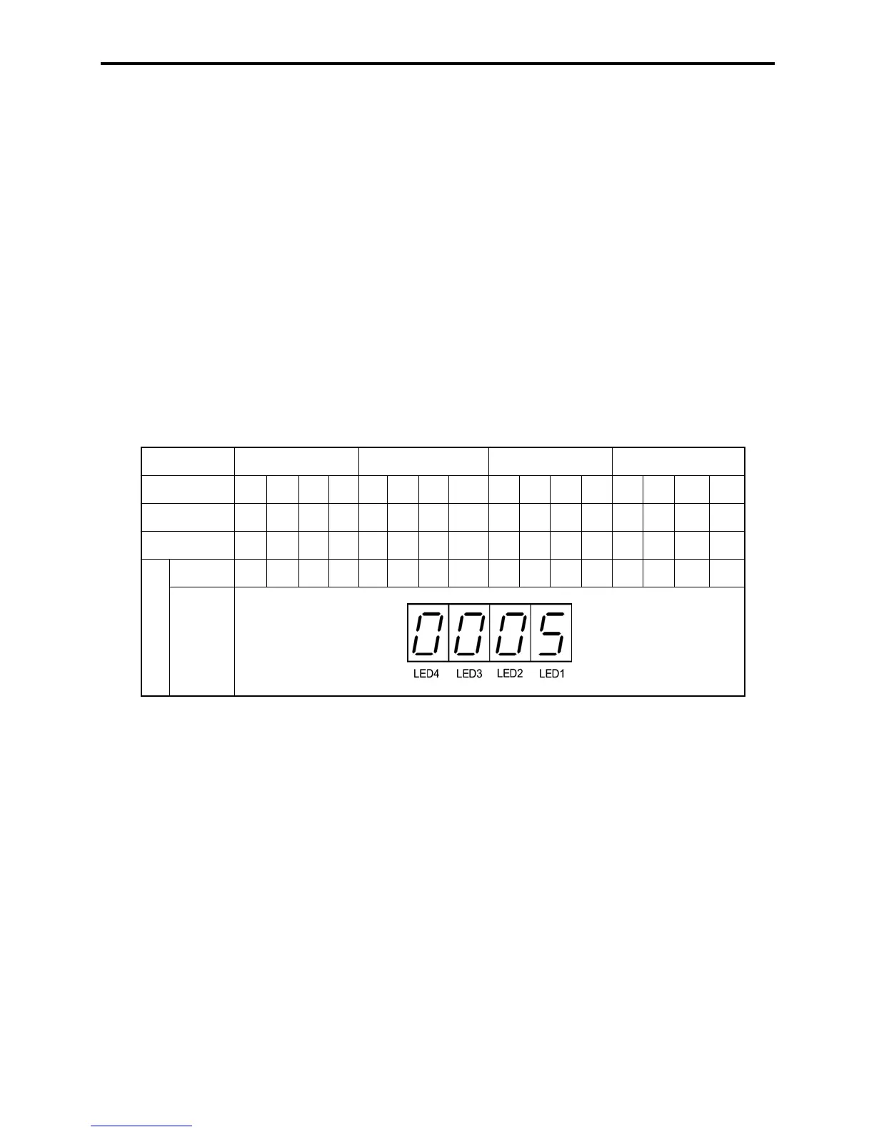
With the FRENIC-Mini, digital input terminals [FWD] and [REV] are assigned to bit 0 and bit 1,
respectively. Terminals [X1] through [X3] are assigned to bits 2 through 4. The value "1" is set for each
bit when the assigned input terminal is short-circuited (ON) with terminal [CM]. The value "0" when it
opens (OFF). For example, when [FWD] and [X1] are ON and all others are OFF, the display on LED4
to LED1 would be 0005.
Bit 0 is assigned to digital output terminal [Y1]. The value "1" is set when the terminal is short-circuited
with [Y1E], and the value "0" is set when it opens. The status of the mechanical relay contact output
terminal [30A], [30B] and [30C] are assigned to bit 8. The value "1" is set when the circuit between
output terminals [30A] and [30C] is closed and the value "0" when the circuit between [30B] and [30C]
is closed. For example, if [Y1] is ON and the circuit between [30A] and [30C] are short-circuited with
each other, then the display for LED4 to LED1 would be 0101.
How the hexadecimal display is configured for the terminals to which bits 0 to 15 are assigned and the
7-segment LED is shown below.
Table 3.11 Segment Display for I/O Signal Status in Hexadecimal Format
LED No. LED4 LED3 LED2 LED1
Bit 15 14 13 12 11 10 9 8 7 6 5 4 3 2 1 0
Input terminal (RST)* (XR)* (XF)* - -- - - --- [X3] [X2] [X1] [REV] [FWD]
Output terminal
- - - - - - -
[30A/C]
- - - - - - - [Y1]
Binary 0 0 0 0 0 0 0 0 0 0 0 0 0 1 0 1
Example
Hexa-
decimal
on the
LED
monitor
– : No correlating control terminals
* (XF), (XR), and (RST) are reserved for communications. Refer to "[ 2 ] Displaying control I/O signal terminals under
communication control" below.
[ 2 ] Displaying control I/O signal terminals under communication control
There are two control circuit input displays under communications link control – "display with ON/OFF
of the LED segment" and "in hexadecimal format" for input commanded from RS-485 communications
link. The content is similar to that of the control circuit I/O signal terminal status display; however, (XF)
and (XR) are added as inputs and nothing is assigned as output terminals.
Refer to the RS-485 Communication User's Manual for details on command inputs through
RS-485 communication.

 Loading...


