3. Machine Set Up QD002-07
42 NXT Setup Manual
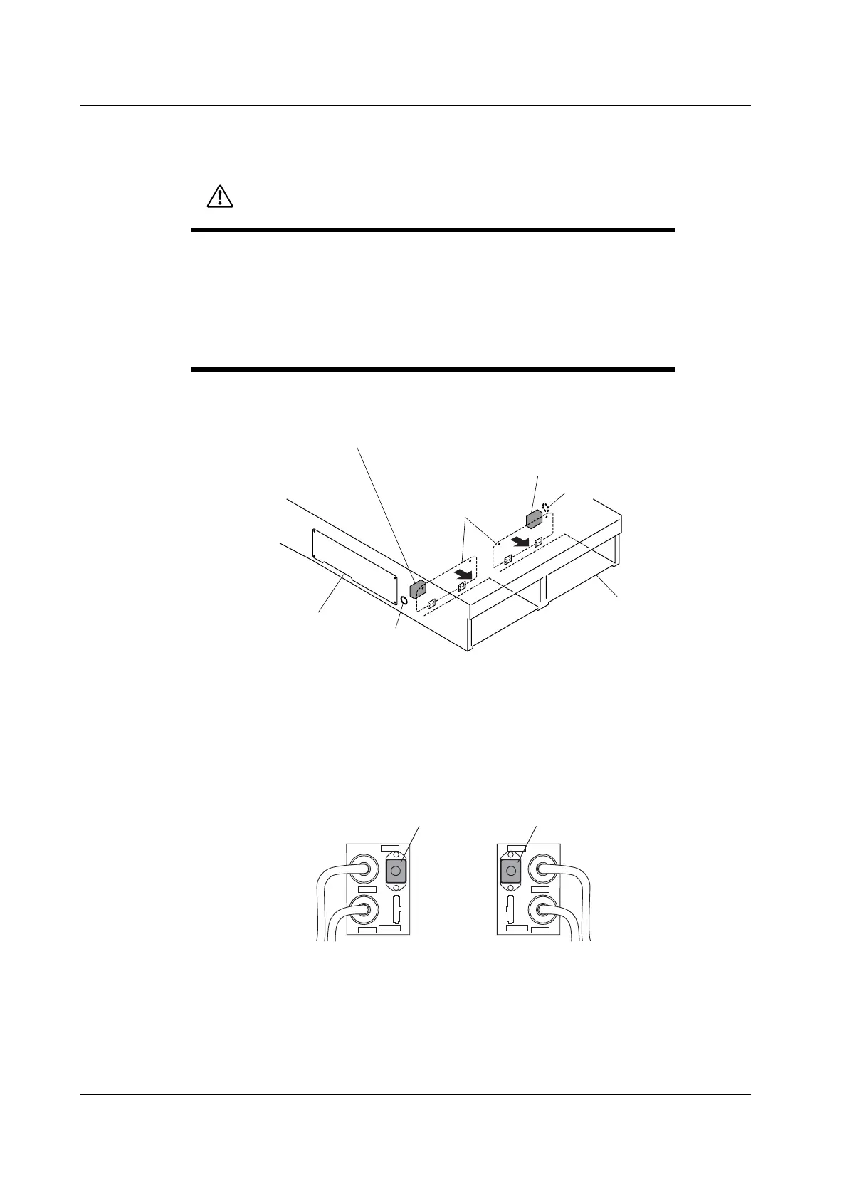
3.7.1 Connecting Method
1. Either open cover A at the front of the base, or remove cover B at the side of the base.
2. Connect the communication cables to the following connectors.
• Connectors LANE1 and LANE2 of the previous stage panel loading I/F box.
• Connectors LANE1 and LANE2 of the next stage panel loading I/F box.
3. Keep the connectors (RH0067* and RH0070*) attached to CN-M1 in the previous stage
panel loading I/F box and CN-M2 in the next stage panel loading I/F box.
CAUTION
Be sure to turn off the power to the machine before connecting or
removing any cables.
Ensure that the connector position is correct by checking the
connector label when connecting connectors.
Be sure to firmly secure the connectors together.
NXTBAS101Ea
Front cover
Hole
Hole
Next stage panel loading I/F box
Previous stage panel loading I/F box
Side cover
Base
CN-M1 CN-M2
CN-CV1F CN-CV1F
LANE1
LANE2
LANE1
LANE2
NXTSET217E
Previous stage panel loading I/F box
Next stage panel loading I/F box
Connector (RH0067*) Connector (RH0070*)