3. Machine Set Up QD002-07
64 NXT Setup Manual
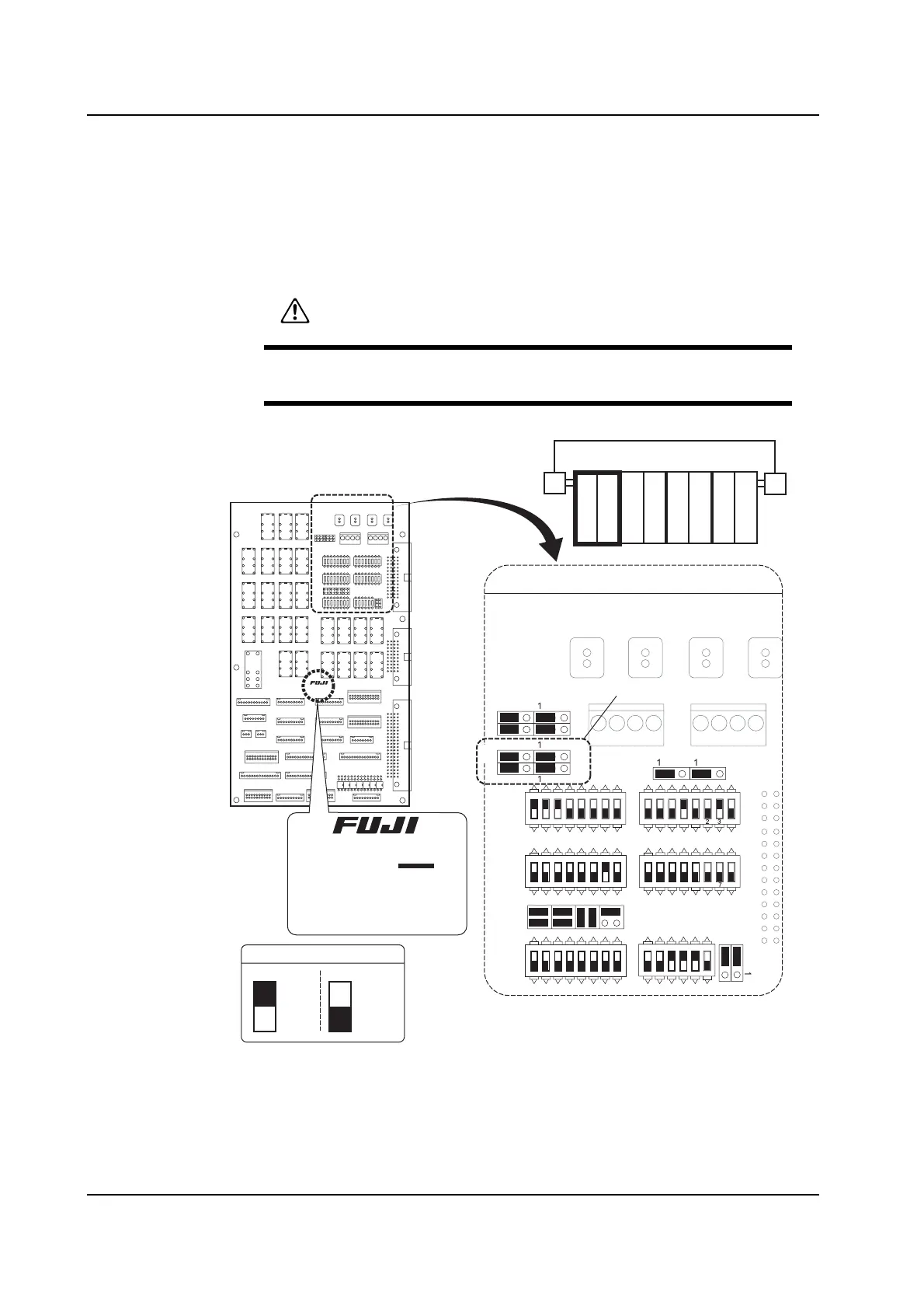
3.8.6 Using Four 2M Bases
Setting the Jumper and DIP Switches
Set the jumper switches and the DIP switches on the interface board and the remote I/O
board in the base as shown in the diagram below. Refer to the "NXT Mechanical
Reference" for details of the location of each board.
CAUTION
Ensure the power to the machine is off before carrying out this
procedure.
FH1211E0
FH1211E0
The dip switch settings
for only boards with E0
at the end are different.
Interface board in the
base control box
DIP switch
ON
ON
ON OFF
JP2-2
JP2-1
P2-
P2-
123
123
123
JP4
-1
JP5
P
-
P
P1-
P1-
P
A
DP1AD
DP1 DP3
JP3-1
JP3-2
JP3-5
JP3-6
1 2
3 4
1 2
3 4
DP7
DP6
JP
-
JP
-
ONON
ON
ON
ON
1234 5
1234 56
78
1234 5
1234 56
78
1234 56
78
1234 1
For boards E
2M 2M
12
3 4
2M
56
2M
78
NXTSET069Ea