QD002-07 3. Machine Set Up
NXT Setup Manual 55
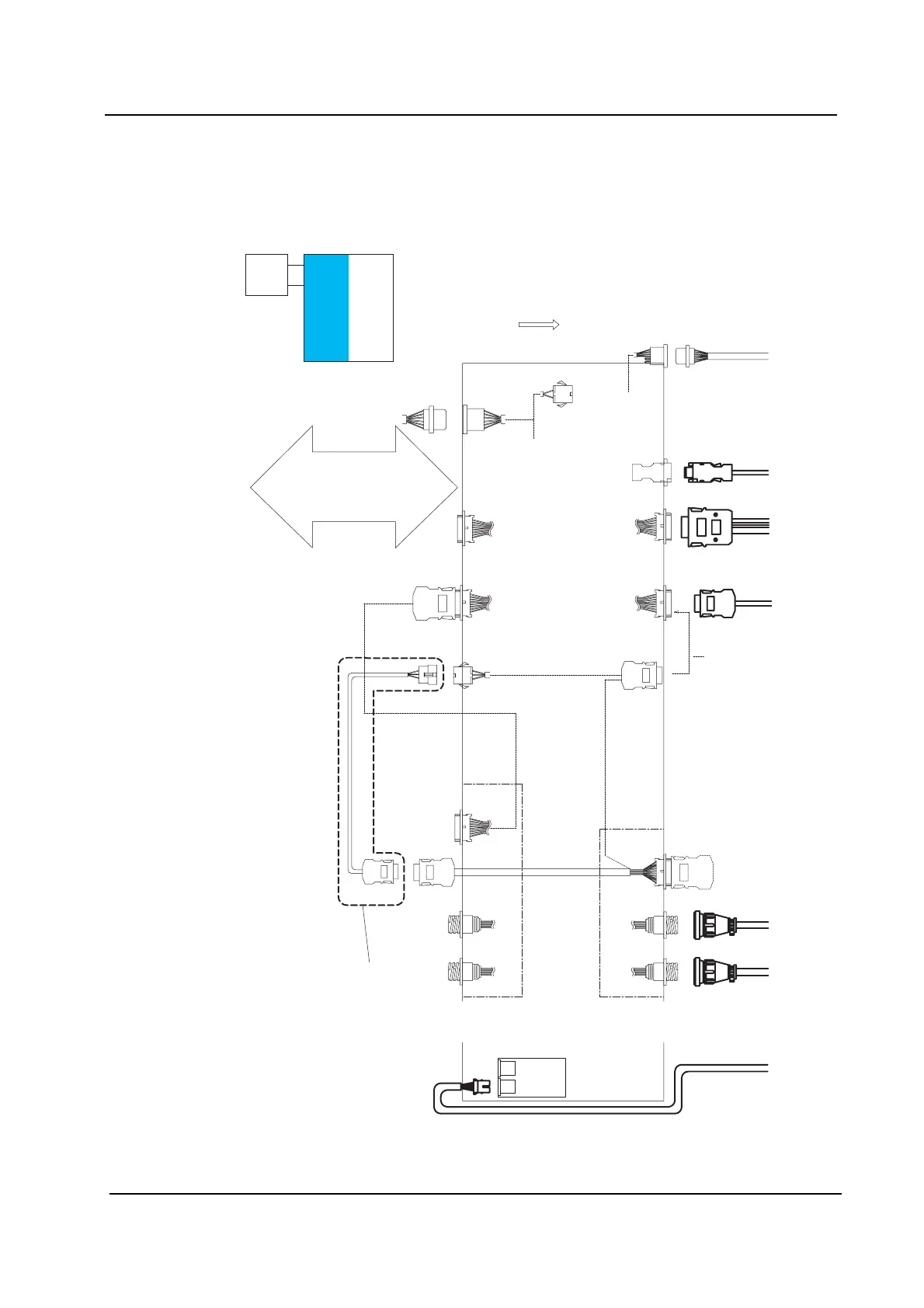
Signal Cable Connection Diagram
(Stand-alone Control Box - 2M Base - 2M Base)
Connect each signal cable as shown in the following diagram.
Note: Base connection harness AJ457** are shown in bold.
Stand-alone Control - 2M Base - 2M Base
Harness Connection Diagram (1/2)
A
B
C
D
E
F
G
Not necessary
Panel flow
CN28B
CN27A
Left side
module cover
RH0527*
To I/F CN27
BRCN1
BRCN2
BRCN2
BLCN2
BLCN3
BLCN4
BRCN3
(Fixed)
BLCN3
BRCN3
(Cable)
BRCN3
BRCN3
RH1162*
CN-M1
CN-M2
Lane 2-R
Lane 1-R
Lane 2-F
CN-M2CN-M2
Lane 1-F
CN-M2
CN-M2
RH1186*
RH1186*
Circuit breaker bracket
CN-1
RH0562*
CN-2
RH1163*
CN-M2
To I/F CN28
2M base
RH2012*CN28A
RH0558*
RH0559*
RH0560*
Disconnect RH0584*,
then connect RH0559*.
Connected when
the base is used
in the last stage.
Connected when
shipped
RH0070*
For connection to the stand-alone
control box, follow the procedures
described in "Using one 2M Base"
except otherwise specified.
NXTSET188Ea
Panel loading
signal bracket
(Previous stage)
Panel loading
signal bracket
(Next stage)