114 Options Guide RX300 S2
Configuration diagram Appendix
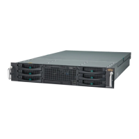
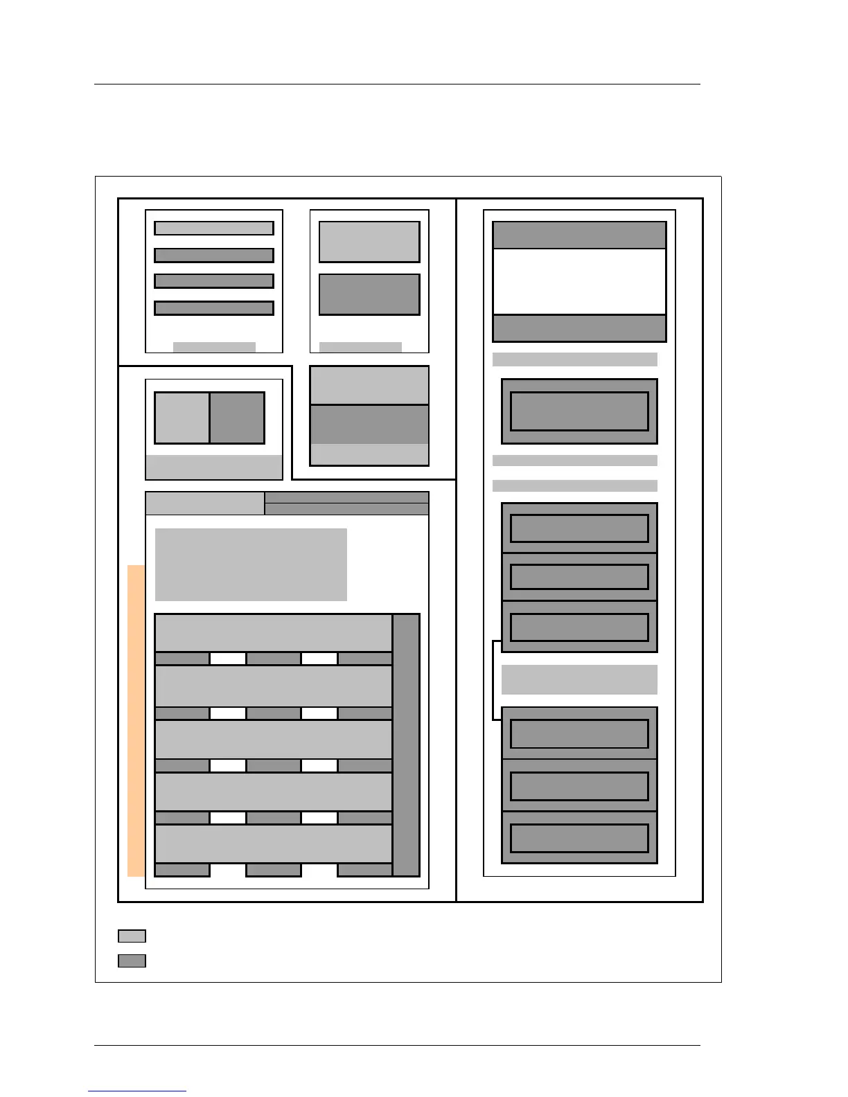
16.2 Configuration diagram
Figure 95: part1 of the system configurator
board front side
middle
Bank I (2 Modules)
Bay for LocalView LCD
Xeon DP
or 3.5"x 0,5" Floppy disk
Bank II (2 Modules)
Bank III (2 Modules) Air channel
Xeon DP
Bank IV (2 Modules)
Bay for 5,25"x 0,5" IDE-CD
or DVD-ROM
Memory ( III ) Processor ( II )
Accessible drives ( V )
rear side
Fan 1 - Fan 4
1. PSU 2. PSU
Needs space for 2
hard disk drives!
Fan 5 - Fan 8 3.5"x1,6"
Redundant system-
HOT PLUG RISER option
Slot 5: PCI-X 64-Bit / 133MHz, Low Profile 3.5"x1" ID 3
Slot 6: Slot 7: Slot 8:
HOT PLUG Standard configuration is
Slot 4: PCI-X 64-Bit / 133MHz, Low Profile single channel
channel 2 (optional) right side
PCI-X 64 PCI-X 64 PCI-X 64
133MHz with IOOP™
Slot 3: PCI-X 64-Bit / 100MHz, Low Profile 3.5"x1" ID 2
100 MHz 100 MHz 100 MHz
Slot 2: PCI-X 64-Bit / 100MHz, Low Profile 3.5"x1" ID 1
Standard Standard Standard
Slot 1: PCI-X 64-Bit / 100MHz, Low Profile 3.5"x1" ID 0
short short long
Key:
Included in basic unit
Option
PCI-Bus
2nd
All
low profile slots are covered, if PCI-riser card configured
3rd
1st
1st
1st

 Loading...