Condensate drains are provided on the boiler. These drains must be connected to a drainage point
on site. All pipework and ttings in the condensate drainage system MUST be made of plastic - no
other materials may be used.
Each module is provided with a condensate trap, the pipe size from the trap outlet is 22 mm.
The routing of the drain must be made to allow a minimum fall of 1 in 20 away from the boiler,
throughout its length.
Connect a condensate drain to each outlet and pipe to a suitable drain point preferably within the
building.
IMPORTANT NOTE: Any external runs must be kept to a minimum and insulated to avoid freezing in cold weather
causing blocking.
2.15
CONDENSATE DRAIN
2.16
WATER AND GAS HEADER INSTALLATION (OPTIONAL EXTRA)
Water and gas header systems can be supplied as fully assembled self supporting units capable of
connecting the water and gas services direct to the rear of the module/s. Each header system
will be individually tailored to specic site/installation requirements. This is an optional extra, as
detailed in Section 1.3, please contact Fulton for further details/designs.
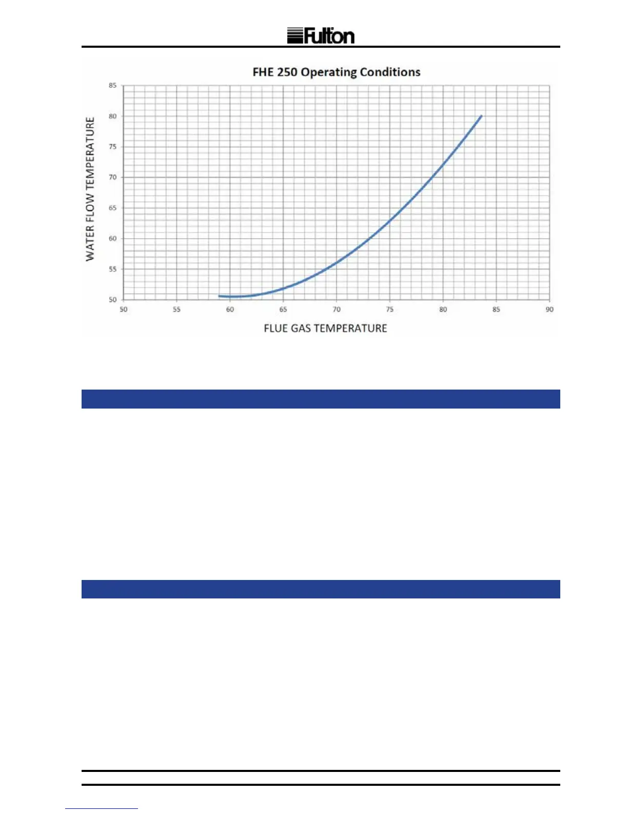
FIG. 4 FLUE GAS CONDITIONS