3.14.9
LOCAL INSTALLER MODE
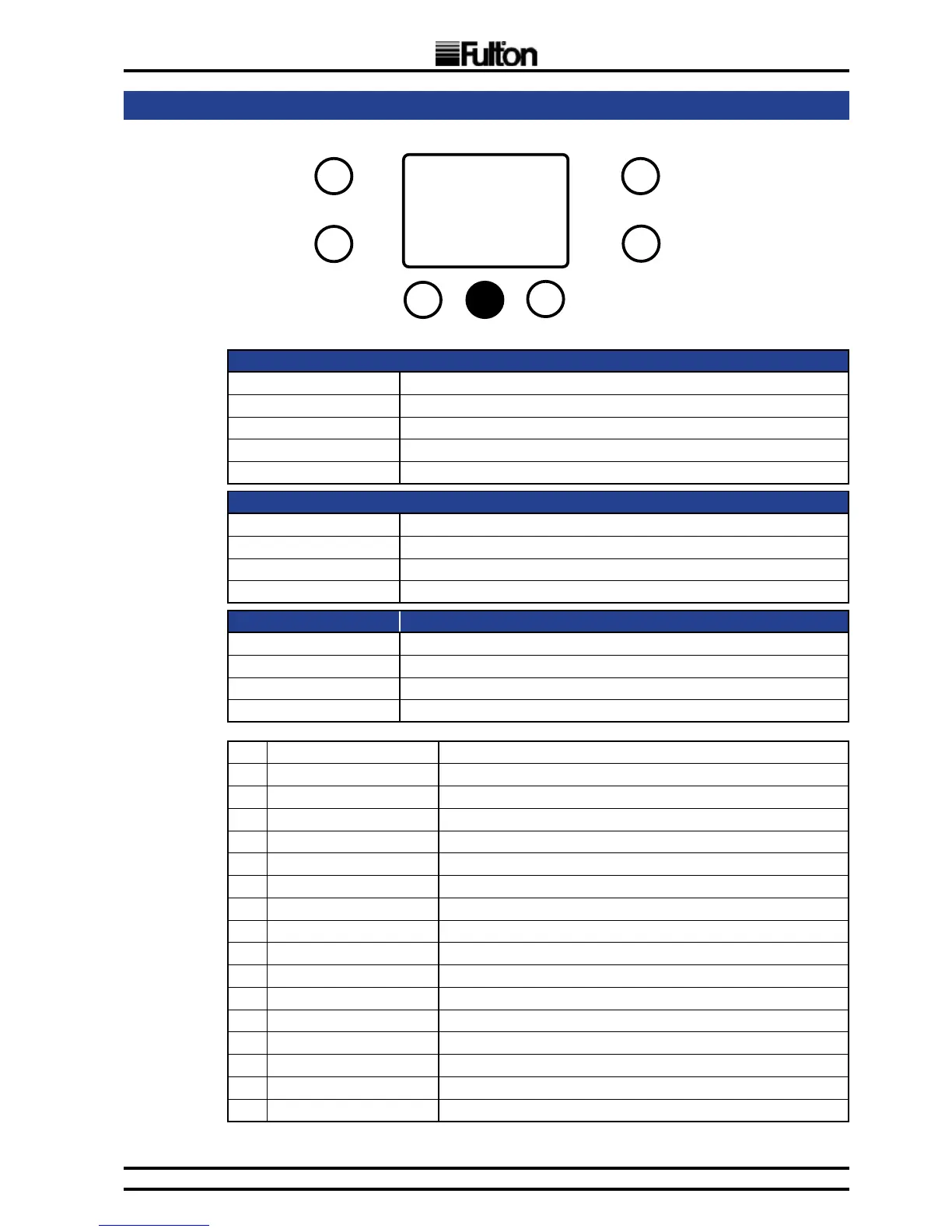
LCD -when showing the parameter index:
seg1 Displayed “P”
seg2 to seg3 Index number (starting from 1)
i1 Installer mode indication
P6 Blinking when MAXSYS0 as the source is selected
P3 Blinking when MAXSYS1 as the source is selected
LCD -when showing the parameter value:
seg1 to seg3 Numeric value (refreshed every 3 sec.)
i1 Installer mode indication
P6 Blinking when MAXSYS0 as the source is selected
P3 Blinking when MAXSYS1 as the source is selected
Button Press: Function:
B for 3 sec. Exit local installer mode
Briey A Exchange burners (in case of two burners per display)
D Decrement index number
E Increment index number
P01 Flame current [uA]
P02 CH supply temperature [ºC -or-ºF]
P03 CH return temperature [ºC -or-ºF]
P04 DHW temperature [ºC -or-ºF] (only on MAXSYS0, if used)
P05 Water pressure [bar/10 -or-psi] (local MAXSYS0, where sensor is connected)
P06 Output level [rel. %] Actual relative output level of the burner
P07 Requested fan speed [50*rpm] Speed requested by control algorithm
P08 Actual fan speed [50*rpm] Fan speed
P09 Exhaust temperature [ºC]
P10 Cascade temperature [ºC -or-ºF], if cascade sensor is connected
P11 OTC temperature [ºC -or-ºF] temperature from external sensor
P12 Cascade mod. level [rel. %] relative modulation level of cascade
P13 CH control setpoint [ºC -or-ºF]
P14 DHW control setpoint [ºC -or-ºF]
P15 Total burners Total count of installed burners
P16 Total burners on Count of burners running
P17 Total displays Total count of boiler modules
Note: MAXSYS0 refers to a unit with LCD display and MAXSYS1 refers to a unit without display.
A
B
C
E
D
G
F
B for 3 sec.