Heat Demand
1. A thermostat (or a volt free contact) can be wired into screw terminals for CH and/or DHW as
applicable to the installation.
2. An external controller with OpenTherm communication port can be wired into the boilers. In this
case the controller will generate the required setpoint for CH only. This needs to be wired
parallel to all of the boilers. Please nd the supported OpenTherm system messages in the
table below.
Master
Boiler
Slave 1
Boiler
Slave 2
Boiler
Slave 3
Boiler
15
14
17
16
19
18
20
15
14
17
16
19
18
20
15
14
17
16
19
18
20
15
14
17
16
19
18
20
ID Read/Write Description
0 R Status
1 W Control Setpoint
5 R Fault ags/code
2 W Master Conguration (dummy write)
3 R Slave Conguration
4 W Lockout Reset
17 R Relative Modulation Level
25 R CH Water Temperature
For details of the terminal connections to use for the thermostat(s) and OpenTherm controller, refer
to the tables in Section 2.19.2 of this manual.
Cascade Temperature Sensor (Header Sensor)
A cascade temperature sensor is provided to monitor the desired set point temperature to
control the boiler outputs. This needs to be placed after the boiler header at an appropriate point in
the system ow pipework.
The sensor needs to be wired in parallel to all of the boilers.
Boiler Status Signals
A normally open volts free contact is provided to indicate a fault of the boiler to remote system
controls. Please refer to the tables in Section 2.19.2 - Terminal Connections for External Wiring.
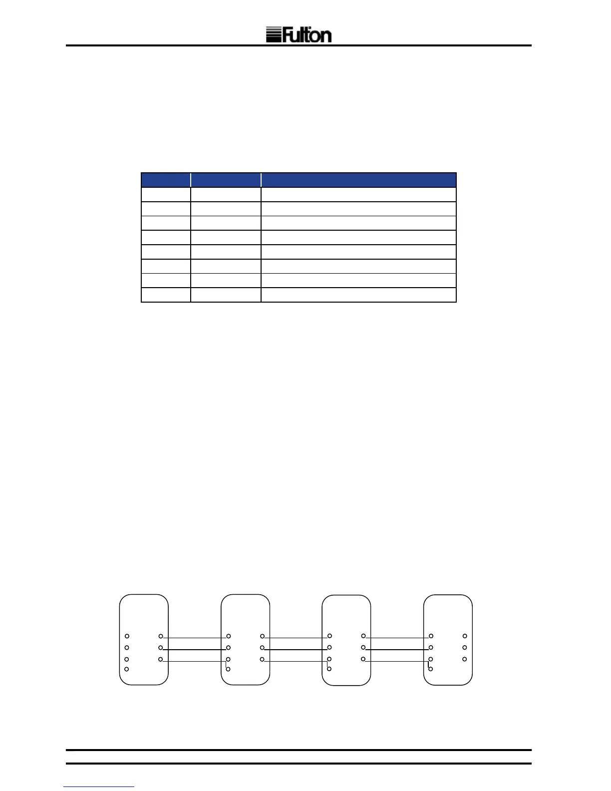
Boiler Communication Cables
The gure below shows the wire connections between the boilers in a cascade system.
* Link Terminal 19 and 20
FIG. 6 BOILER COMMUNICATION CABLES